technical · Article
The Heartbeat Cycle: 200 ms That Keep Modern Metros Safe

A CBTC line operating at 90-second headways is a distributed real-time computing system that has to make a million coordinated decisions per train per service day. The single mechanism that holds all those decisions together is the heartbeat cycle: the 500 millisecond to 1 second loop in which every train sends a fresh position report up to its Zone Controller, every Zone Controller computes a fresh Movement Authority for every train in its territory, and every Authority comes back down to the train in time for the next loop. The Washington Metropolitan Area Transit Authority (WMATA) Red Line CBTC overlay, the New York 7 Line, and the BART Train Control Modernization Program (TCMP) all run different cycle times and different latency budgets — but all three are built around the same architectural metronome. Understanding what happens in a 200 ms slice of that cycle is how a signaling engineer understands why a 100 ms latency improvement can buy 8 to 12 seconds of headway margin.
Why the heartbeat is the architectural metronome
Manuscript Chapter 3.4 frames the heartbeat as the cycle that drives all downstream operations: shorter cycles enable tighter headways and faster response to changing conditions; longer cycles reduce communication bandwidth requirements but cap achievable capacity. The cycle is fundamentally a distributed-systems consistency mechanism. At any instant, each Zone Controller holds an authoritative view of every train in its zone; every train holds an authoritative view of its current Movement Authority. The view stays consistent because the system refreshes both halves at a fixed cadence. This article is for the signaling engineer, ATP architect, system integrator, and Independent Safety Assessor who need to understand what happens in each phase of the cycle and how the latency budget connects to the rest of the system. Depth lives in Chapter 3 (System Architecture) and Chapter 6 (Communication Systems) of Communications-Based Train Control, Volume 1.
The cycle in one sentence and one diagram
A heartbeat cycle, end to end, is: the Vehicle On-Board Controller (VOBC) builds a position report; the report goes up the radio link to a Wayside Access Point and on to the Zone Controller (ZC); the ZC integrates the report with reports from every other train in its zone, the interlocking state, and the temporary speed restrictions; the ZC computes a fresh Movement Authority (MA) for each train; the MA goes back down the radio link to the VOBC; the VOBC validates the MA and uses it to update the ATP speed envelope; and the entire cycle repeats.
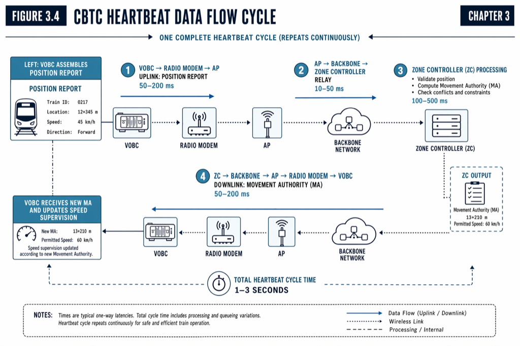 The CBTC heartbeat cycle is a four-phase distributed loop. Each phase has its own latency budget; the sum of all four budgets caps achievable headway.
The standard cycle period for a modern US deployment is 500 ms to 1 second, with some systems running tighter cycles for capacity-critical corridors and looser cycles for less-demanding lines. Manuscript Chapter 3 references WMATA’s Red Line CBTC at a 500 ms cycle, BART’s TCMP at a 1-second cycle, and the L Line and 7 Line at cycles in the same range. The choice of cycle time is a system design decision balanced against radio bandwidth, ZC processing capacity, and the headway target.
The 200 ms slice: what the VOBC does
In a typical 500 ms cycle, the VOBC owns the first 100 to 200 ms. The work breaks into four phases that have to complete every cycle without exception (the cycle structure is documented in detail in The Onboard Side of CBTC: Inside the VOBC).
Phase 1, input ingest (about 5 to 20 ms). The VOBC reads sensor data from tachometers, Doppler radar, balise antenna, accelerometer, and door, brake, and traction status switches. It receives messages from the Data Communication System (DCS) radio and from the Train Management System bus. Each input is range-checked and plausibility-checked against rate-of-change limits and cross-checked against redundant sources where available.
Phase 2, position report assembly (about 10 to 30 ms). The VOBC fuses the sensor data through a Kalman filter to produce a current best-estimate position with associated uncertainty bound, latches the current speed and acceleration, captures door, brake, and traction state, and assembles the position report payload. The payload is typically 100 to 200 bytes, containing train identity, position (track segment and offset), speed, acceleration, door status, brake status, and VOBC health flags.
Phase 3, uplink transmit (about 50 to 100 ms). The DCS radio modem transmits the position report to the nearest Wayside Access Point, which relays it through the wayside backbone (typically a redundant fiber ring) to the responsible Zone Controller. The 50 to 100 ms covers the radio-modem encode and transmit, the over-the-air propagation, the access-point relay, and the backbone hop. Some systems carry redundant uplinks through two access points simultaneously, switching seamlessly if one link degrades.
Phase 4, ATP envelope update (about 30 to 50 ms). While waiting for the next downlink MA, the VOBC’s redundant safety processors compute the four-tier speed envelope (covered in Inside the CBTC Braking Curve: How Safe Stopping Distance Is Calculated) using the current MA and the sensor inputs from this cycle. Outputs are voted (2-out-of-3) or compared (2-out-of-2), and the brake, traction, and Driver Machine Interface commands are issued.
The 200 ms slice: what the Zone Controller does
The Zone Controller’s slice of the cycle runs in parallel with the VOBC’s: while one train is preparing its next position report, the ZC is processing the position reports it received this cycle from every other train in the zone.
Phase A, input collection (about 50 to 100 ms). The ZC receives position reports from all trains in its zone (typically 4 to 12 trains per zone, depending on territory size and zone topology), the interlocking state from the wayside electronic interlocking, temporary speed restriction updates from the Automatic Train Supervision (ATS), and degraded-mode data from neighboring ZCs at zone boundaries.
Phase B, occupancy update and conflict detection (about 50 to 100 ms). The ZC updates its internal track-occupancy model: each train’s current occupied envelope (front position minus uncertainty, rear position plus uncertainty plus train length), each switch position, each work-zone or temporary speed restriction. The ZC then runs conflict detection: which trains’ projected paths overlap, where switch routes are pending, where track-circuit-detected non-CBTC trains require buffer.
Phase C, MA computation (about 100 to 300 ms). For each train in the zone, the ZC computes the new MA: the End of Authority (EoA) point, the applicable speed restrictions along the path to EoA, the temporary speed limits, and the validity timestamp. The MA is signed against the safety integrity protections — cryptographic authentication, sequence numbering, and cyclic redundancy check (CRC) — and queued for downlink.
Phase D, downlink transmit (about 50 to 100 ms). The MA is transmitted from the ZC through the wayside backbone, the relevant Wayside Access Point, and the radio link to the VOBC. The downlink mirrors the uplink in latency budget. Some systems use the same radio channel for both; some use separated channels.
The ZC also produces an aggregated zone status report at 1 to 2 second cadence, transmitted to the central ATS for line-level optimization, dispatcher display, and conflict detection across zone boundaries.
End-to-end latency: the hard ceiling on headway
Manuscript Chapter 3.4 documents the end-to-end latency from a train’s position change to the corresponding MA update reaching that train as typically 1 to 3 seconds for normal operation, allocated across stages: VOBC processing and report assembly (50 to 100 ms), radio transmission and access point relay (50 to 200 ms), ZC processing and MA computation (100 to 500 ms), and return radio transmission (50 to 200 ms).
If total latency exceeds the budget, the system’s assumed worst-case train position uncertainty grows. The ATP must then reserve a larger Supervised Location offset, which extends the EBD, which forces a wider headway. A 100 ms latency improvement at 80 km/h saves 22 m × 0.1 s = roughly 2.2 m of position uncertainty growth, which compounds into 8 to 12 seconds of additional headway margin in a 90-second-headway design. The arithmetic is small per cycle but compounds across thousands of cycles per train per day.
Communication loss timeout: the safety counter to latency
Manuscript Chapter 3.4 names a critical safety parameter that the heartbeat cycle structure depends on: the communication loss timeout, typically set at 3 to 5 seconds. If a VOBC does not receive an MA update within this window, it assumes communication has failed and initiates a safe stopping protocol — applying service braking to bring the train to a controlled stop within its last valid MA.
The timeout interacts with the heartbeat cycle in two ways. First, it sets a floor on cycle period: cycles much shorter than the timeout produce many missed cycles before the timeout triggers, but the safety logic still works. Second, it interacts with headway directly. A 3 second timeout permits brief radio dropouts of one to four cycles without triggering a stop; a 5 second timeout permits longer dropouts but requires larger safety margins because trains continue under the cached MA for longer. The communication-loss behavior is covered in detail in Communication-Loss Fallback: How Trains Behave When the Radio Drops.
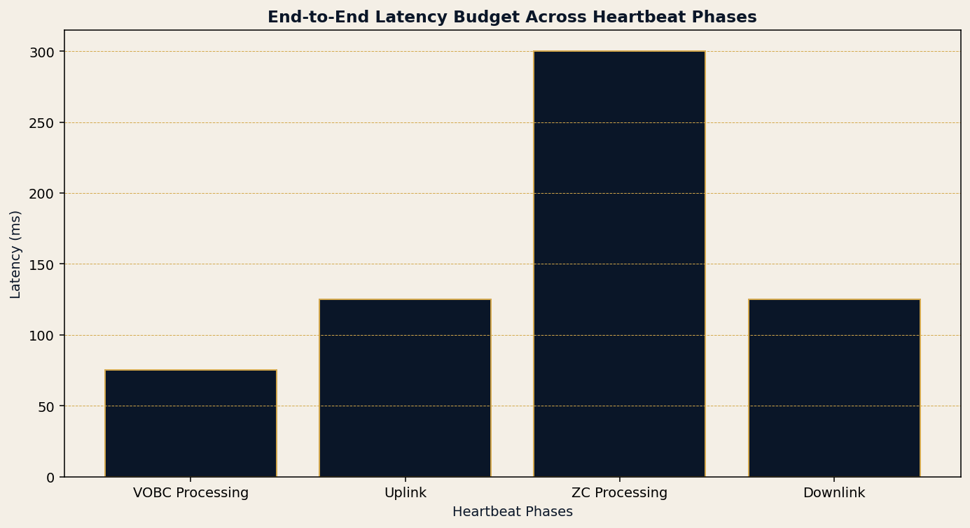 End-to-end latency budget across the four heartbeat phases. Cycles that exceed the budget force wider position-uncertain.
Redundancy at every layer
Given that the heartbeat is the safety-critical path, redundancy is engineered into every layer. At the radio level, most deployments provide overlapping coverage from adjacent Wayside Access Points so a single AP failure does not create a communication gap; some systems run dual-radio architectures where the VOBC maintains simultaneous connections to two APs and switches seamlessly if one degrades. At the network level, the fiber backbone connecting Zone Controllers to the central ATS uses redundant ring or mesh topologies so a single cable cut does not isolate any zone. At the protocol level, every message carries sequence numbers for out-of-order detection, CRC for corruption detection, and timestamps for freshness verification — stale or corrupted data is rejected before it can affect a safety decision.
The Zone Controller itself is typically deployed with hot-standby redundancy: a primary ZC handles all traffic while a secondary ZC maintains synchronized state in real time, ready to take over within milliseconds if the primary fails. Manuscript Chapter 3.3 references hot-standby as the dominant US architecture; the trade-off against cold standby is hardware cost (roughly twice the equipment) versus recovery time (milliseconds versus minutes).
Bandwidth: smaller than most engineers expect
A common misconception is that CBTC requires high radio bandwidth. The math says otherwise. A 200-byte position report at 1 Hz per train is 1.6 kbit/s per train. A 100-train fleet at the same rate is 160 kbit/s of uplink — comfortably within the capacity of any 2.4 GHz or 5 GHz spread-spectrum radio system. Add MA downlink, ATS updates, and overhead, and total CBTC payload is in the 50 to 200 kbit/s range per zone.
What matters is not bandwidth but determinism. The heartbeat cycle requires that each message arrive within its latency budget with high probability. Spread-spectrum radio at 2.4 GHz or 5 GHz provides the bandwidth easily; the engineering work is in coverage planning, interference management, and handover (the wireless coverage and handover details live in Chapter 6 of the manuscript). LTE-R and 5G-based deployments offer higher bandwidth and arguably better coverage but introduce latency variance that has to be carefully managed against the cycle budget.
Practical implications for design
Three system-design implications fall out of the heartbeat structure. First, cycle period is a deliberate trade between headway capacity, radio bandwidth, and ZC processing capacity. A 500 ms cycle supports tighter headways but doubles the message rate against a 1-second cycle. Second, the latency budget is the binding constraint that connects the radio architecture, the wayside backbone, and the headway target. Designers who optimize one element of the budget without considering the others typically discover that they have not improved the headway they thought they had. Third, the communication loss timeout sets the limp-home behavior of the system. A 3-second timeout produces a more responsive safety case but is less tolerant of brief radio dropouts; a 5-second timeout is more tolerant but produces a less aggressive headway floor.
Practical takeaways
- The heartbeat cycle is the architectural metronome of every CBTC system. Its period (typically 500 ms to 1 second) and end-to-end latency (typically 1 to 3 seconds) together set a hard ceiling on achievable headway.
- The cycle is a four-phase loop: VOBC position report assembly, uplink, ZC processing and MA computation, downlink. Each phase has its own latency budget; the sum determines the system’s position-uncertainty growth and Supervised Location offset.
- A 100 ms improvement in cycle latency at 80 km/h compounds into roughly 8 to 12 seconds of headway margin. The arithmetic is small per cycle and large per service day.
- Redundancy is engineered into every layer (radio, backbone, protocol, ZC) because the heartbeat is the safety-critical path. The communication loss timeout (typically 3 to 5 seconds) is the safety counter that triggers safe stopping when the heartbeat fails.
- CBTC bandwidth requirements are modest (50 to 200 kbit/s per zone). The engineering work is in determinism, not throughput.
Where to go next
This post is a 10-minute walk through the heartbeat cycle. The full architecture and communications treatment lives in Chapter 3 (System Architecture) and Chapter 6 (Communication Systems) of Communications-Based Train Control, Volume 1: Foundations & Technical Architecture (Buy on Amazon). Download Chapter 3 slides (free PDF) for the architecture and data-flow diagrams.
For the onboard cycle in detail, see The Onboard Side of CBTC: Inside the VOBC. For how the system behaves when the heartbeat fails, see Communication-Loss Fallback: How Trains Behave When the Radio Drops.
Sources
- Wang, C. (2026). Communications-Based Train Control, Volume 1: Foundations & Technical Architecture. Independent. ISBN 979-8-258-54295-3. — Chapter 3, “CBTC System Architecture Overview,” section 3.4; Chapter 6, “Communication Systems.”
- IEEE Standards Association. IEEE Std 1474.1: Communications-Based Train Control (CBTC) Performance and Functional Requirements.
- IEEE Standards Association. IEEE Std 1474.2: User Interface Requirements in Communications-Based Train Control (CBTC) Systems.
- IEEE Standards Association. IEEE Std 802.11: Wireless LAN Medium Access Control (MAC) and Physical Layer (PHY) Specifications.
- Federal Transit Administration. (2016). FTA Report No. 0045: Communications-Based Train Control (CBTC) Technology. transit.dot.gov
- MTA New York City Transit. Communications-Based Train Control Status Update. new.mta.info/project/communications-based-train-control-cbtc
- Washington Metropolitan Area Transit Authority. Automatic Train Control Modernization. wmata.com
- Bay Area Rapid Transit. Train Control Modernization Program. bart.gov/about/projects/cbtc
Read the full treatment in the book
Chapter 3 of Communications-Based Train Control, Volume 1, covers this in depth.