technical · Article
Communication-Loss Fallback: How Trains Behave When the Radio Drops

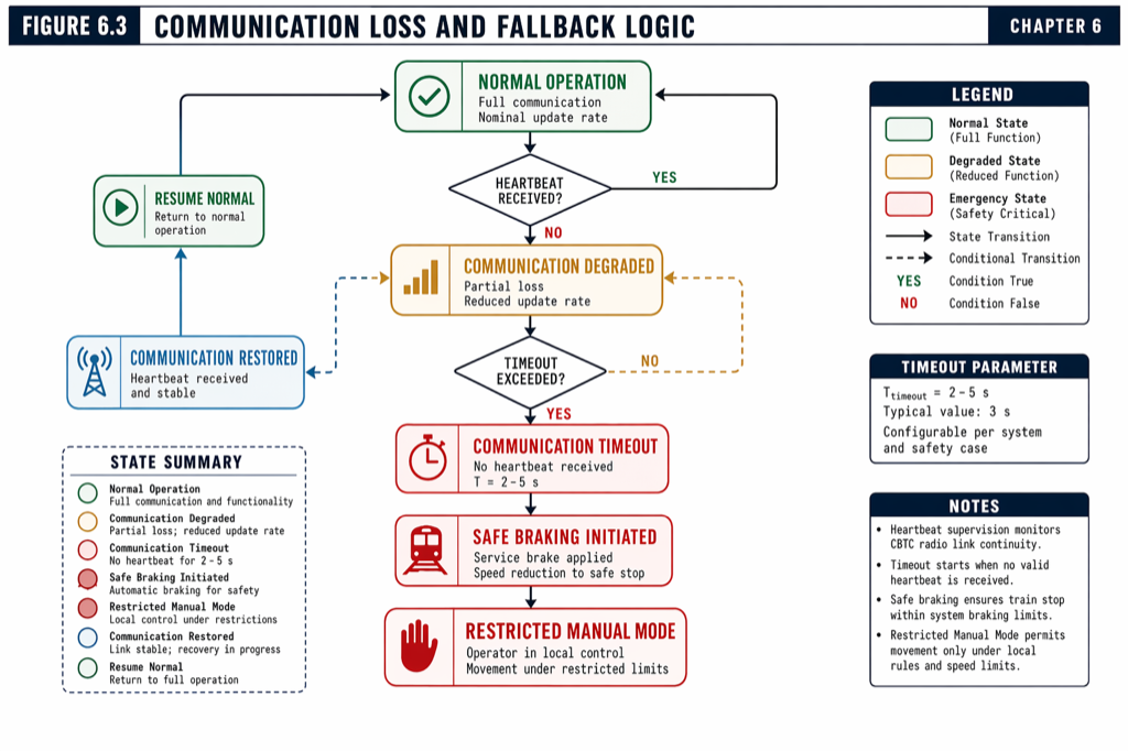
The Communications-Based Train Control (CBTC) heartbeat cycle is the architectural metronome that keeps every train and every Zone Controller (ZC) consistent. When the radio link drops — a packet is corrupted, a Wayside Access Point fails, an interfering radio source jams the channel — the metronome stops. Modern CBTC systems are designed so that the metronome can stop briefly without jeopardizing safety: 3 to 5 seconds of no Movement Authority (MA) updates is a routine event the system tolerates by continuing under the cached MA. Beyond the timeout, a coordinated staircase of degraded-mode responses brings the train to a controlled stop, then to a recoverable state, then back to normal CBTC operation. The staircase is what separates a CBTC line that survives transient radio interference from one that erupts into service-affecting cascades whenever the wireless gets noisy.
Why the fallback architecture is the line’s reliability story
A US heavy-rail transit line operating under CBTC averages thousands of train-radio cycles per service day. The probability of a successful cycle is high but never one. Manuscript Chapter 3.4 cites a typical communication-loss timeout of 3 to 5 seconds — the safety counter that sets the boundary between transient dropout and confirmed loss. Below the timeout, the train continues under cached MA and the system absorbs the dropout with no operational consequence. Above the timeout, the safe stopping protocol fires, and how the train and the wayside coordinate from there determines whether the line recovers in seconds or minutes. This article is for the signaling engineer, ATP architect, system integrator, and Independent Safety Assessor who need to understand the fallback staircase and the trade-offs each step embodies. Depth lives in Chapter 3, Chapter 6, and Chapter 9 of Communications-Based Train Control, Volume 1.
Step 0: a missed cycle is not a failure
The first thing the architecture has to handle gracefully is a single missed cycle. A 500 ms or 1 second heartbeat cycle (covered in The Heartbeat Cycle: 200 ms That Keep Modern Metros Safe) is short enough that occasional message loss is statistically expected. The Vehicle On-Board Controller (VOBC) holds the most recently received MA in cache, and the safety logic continues to enforce the cached MA’s speed envelope.
The cached-MA approach has a built-in time horizon. Each MA carries an End of Authority (EoA) that bounds the train’s allowed travel; as the train approaches the EoA without an MA extension, the speed envelope continuously tightens. The train will physically stop at the EoA whether or not new MAs arrive — the cache plus the static EoA is a safety floor. This is what allows the system to absorb 1, 2, or 3 missed cycles without action: the train has not yet reached the cached EoA, the speed envelope is still well-behaved, and the next successful cycle will refresh everything.
Manuscript Chapter 3.4 puts the typical communication-loss timeout at 3 to 5 seconds, which corresponds to roughly 4 to 10 missed cycles depending on cycle period. The timeout is set to permit normal radio jitter and brief obstructions while triggering definitive action before the cached MA’s EoA becomes binding at operational speed.
Step 1: the timeout fires — safe stopping protocol
When the timeout expires, the VOBC declares communication lost and initiates the safe stopping protocol. The protocol is conservative and well-defined: apply service brake, decelerate at the certified service rate (typically 0.8 to 1.0 m/s²), and bring the train to a controlled stop within the last valid MA’s EoA. The brake is service, not emergency — the goal is operational continuity, not maximum stopping force, and emergency brake is reserved for situations where the train would otherwise overrun the EoA.
The arithmetic is straightforward. A train at 80 km/h decelerating at 1.0 m/s² stops in roughly 246 m of kinematic distance plus reaction-time and uncertainty margins (the full EBD treatment is in Inside the CBTC Braking Curve: How Safe Stopping Distance Is Calculated). On a 90-second-headway line with 300 m of cached EoA distance from the train at the timeout instant, the safe stopping protocol fits comfortably within the cached MA. On lines that operate closer to their EoA, the protocol may fall back to emergency brake to maintain the safety margin.
Critically, the safe stopping protocol does not require any radio communication. The VOBC executes it autonomously based on the cached MA, the local sensor stack (covered in Train Localization in CBTC: Tachometer + Doppler + Beacon Fusion), and the certified brake performance. This independence is the safety guarantee: even if the radio is permanently lost, the train still stops safely within its last authorized envelope.
 The communication-loss fallback staircase. Each step is a deliberate trade between operational continuity and safety conservatism.
Step 2: limp-home mode
Once stopped, the train enters limp-home mode (sometimes called restricted mode or degraded mode). The behavior is conservative and human-supervised. Manuscript Chapter 4.2 documents the typical limp-home parameters: maximum speed 10 to 20 km/h, manual driver control, reliance on balise reads to constrain position uncertainty, and continuous attempt to re-establish radio communication.
The conservative speed cap matters because the train is operating without continuous MA updates and without the wayside’s view of conflicting trains. Even with a valid cached MA, the absence of MA refreshes means the system cannot extend the EoA dynamically as the train ahead moves, which in normal operation is what keeps the train moving at line speed. At 10 to 20 km/h, the kinematic stopping distance is small enough that the driver can stop within line-of-sight, providing a backup safety mechanism that does not depend on the radio.
The driver in limp-home mode is performing the operational role that fixed-block signaling assumed: line-of-sight following and human-validated movement. This is why CBTC implementations at GoA 1 and GoA 2 (manual or driver-supervised operation) handle communication loss more gracefully than GoA 4 (driverless): there is a human in the cab to take over. GoA 4 driverless deployments require additional architecture (explicit recovery procedures, remote dispatcher control, fallback automation modes) that GoA 2 deployments inherit from the driver’s presence.
Step 3: re-acquisition and position validation
When the radio link is restored — through interference clearing, the failed Wayside Access Point coming back online, or the train moving into coverage of a different access point — the system has to validate that the train can safely return to normal CBTC operation.
The validation is in two parts. First, the radio link itself has to be confirmed: cryptographic mutual authentication, sequence number resynchronization, and CRC validation on a sequence of position reports and MAs. Second, the train’s position has to be validated. During limp-home mode, the localization stack has been operating with degraded confidence; if the train passed multiple balises while the radio was down, the position uncertainty is well-bounded. If the train has been stationary or has passed only odometric distance without balise reads, the uncertainty may have grown beyond the safe-operating threshold.
If position uncertainty is within acceptable limits — typically ±20 to ±50 meters — the ZC issues a fresh MA and normal operation resumes. If uncertainty exceeds limits, the train must continue in limp-home mode until it passes one or more balises that provide absolute position resets. Manuscript Chapter 4.2 documents this recovery sequence: the train detects communication loss and enters limp-home; when communication is restored, the ZC requests a position report; if uncertainty is acceptable, normal operation resumes; if not, the train must reset position before resuming normal speed.
Where the fallback architecture is engineered
The fallback architecture lives in three places in the CBTC stack.
At the protocol layer, message timestamps, sequence numbers, and freshness windows define what counts as a successful cycle and what counts as a miss. Tighter windows produce more sensitivity to brief radio jitter; looser windows tolerate more dropout but slow detection of genuine loss. Manuscript Chapter 6 covers the specific protocol parameters used in modern US deployments.
At the VOBC layer, the safe stopping protocol implementation, the cached-MA logic, and the limp-home mode state machine are part of the SIL 4 vital software. They are validated through the same FMEA, FTA, and HAZOP analyses that validate the rest of the ATP logic, and they are exercised through the testing campaigns documented in Chapter 12 of the manuscript — including degraded-mode scenarios that explicitly induce radio loss to verify behavior.
At the wayside layer, the ZC’s response to a missing train report is governed by symmetric logic. If the ZC has not received a position report from a train it expects to hear from, it does not assume the train is in any particular position; it widens the safety envelope (treats the train’s possible position as the entire region from the last known position to the maximum credible distance the train could have traveled) until either a fresh report arrives or the train is confirmed safely stopped through other means.
What the radio architecture has to deliver
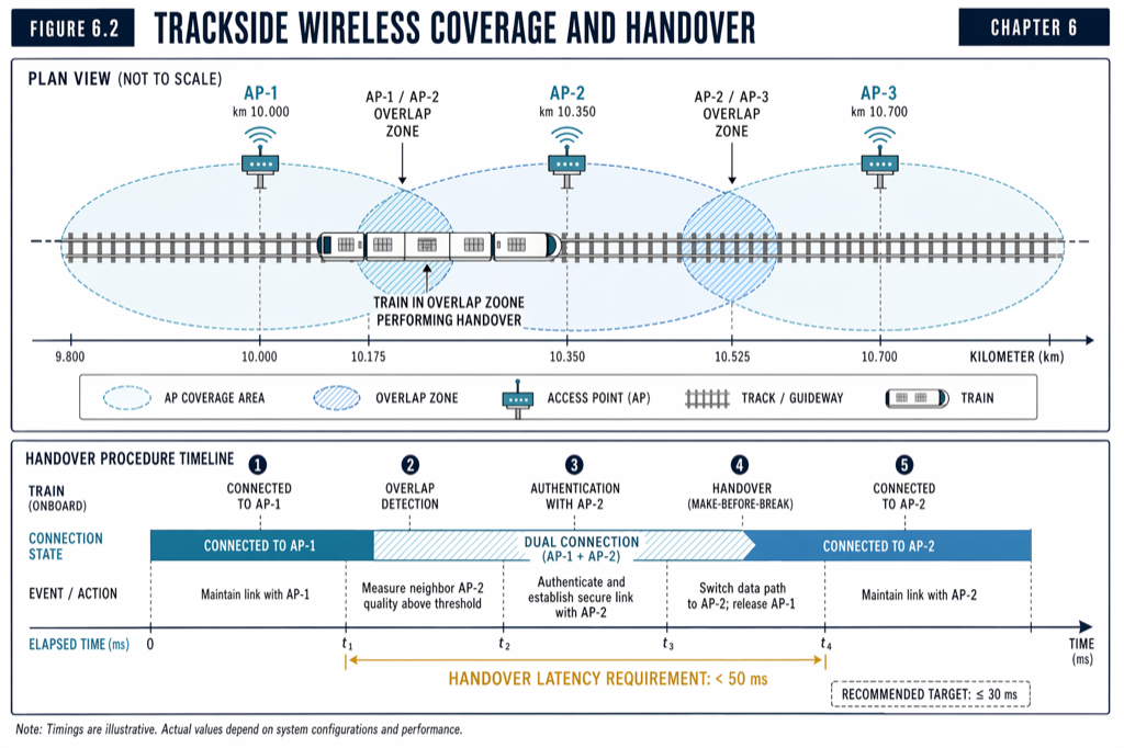
Manuscript Chapter 6 covers the wireless radio architecture in detail; the relevant point for fallback is that radio coverage and handover have to deliver an availability target consistent with the system’s communication-loss tolerance. Three architectural patterns matter most.
Overlapping coverage. Most US deployments provide overlapping coverage from adjacent Wayside Access Points so that a single AP failure does not produce a coverage gap. The handoff between APs is engineered to be seamless within the cycle period: a train passing from AP A to AP B should not miss a cycle. Manuscript Chapter 3.4 documents the redundant ring or mesh fiber backbone topology that supports the coverage.
Dual-radio architectures. Some systems run dual radio modems on each train, maintaining simultaneous connections to two APs. If one link degrades, the other continues seamlessly. Dual-radio doubles the onboard radio cost but eliminates single-radio dropout as a failure mode.
Frequency diversity. CBTC systems typically operate in 2.4 GHz or 5 GHz spread-spectrum bands. Frequency diversity within the band — multiple channels, channel hopping, or frequency-hopping spread spectrum — protects against narrow-band interference. The interference profile in major US cities is harder than in greenfield deployments; Manhattan, downtown San Francisco, and downtown Washington DC all carry substantial 2.4 GHz Wi-Fi traffic that competes with CBTC channels.
The interaction between radio architecture and the fallback staircase is straightforward: the better the radio architecture, the rarer the timeout firing, and the smaller the operational impact when it does. A well-designed radio architecture means the staircase is a safety mechanism that almost never activates rather than an everyday operational feature.
 Overlapping AP coverage and dual-radio onboard architecture together make the communication-loss timeout an exception, not a routine event.
What goes wrong: the failure modes that surface in service
Three failure modes appear regularly in US CBTC operational data and deserve specific design attention.
Sustained interference from a fixed source. A construction radio source, a temporary commercial transmitter, or an unauthorized 2.4 GHz device near the right-of-way can produce sustained interference that drops radio links for tens of seconds at a time. The system’s safe stopping protocol works correctly each time, but the operational impact is multiple trains stopping in sequence — a service-affecting cascade. The fix is interference detection and operational coordination with the source; the architectural defense is frequency diversity.
Coverage gaps at AP boundaries. Imperfect handover between adjacent APs can produce brief coverage gaps that fall into the timeout window. The trains stop, the dispatcher gets alerts, and the trains recover after limp-home — but the operational disruption is real. The fix is RF coverage planning and handover tuning during commissioning.
Correlated faults across redundant subsystems. A single common-mode fault (a shared power supply, a shared timing source, a shared software version with a latent bug) can drop both radio links simultaneously, defeating the dual-radio redundancy. The defense is design-time analysis (the FMEA that addresses common-mode failures) and operational diversity (different power sources, different timing sources where feasible).
Practical takeaways
- The CBTC communication-loss fallback is a staircase, not a single response. Step 0 is “no action — within timeout”; step 1 is the safe stopping protocol triggered by timeout; step 2 is limp-home mode under driver control; step 3 is re-acquisition with position validation before normal operation resumes.
- The 3 to 5 second timeout balances radio-jitter tolerance against safety responsiveness. Tighter timeouts produce more responsive safety cases but are less tolerant of routine dropouts; looser timeouts are more tolerant but require larger safety margins in the EBD calculation.
- Limp-home mode at 10 to 20 km/h under driver control is the bridge between safe stop and normal operation. It is graceful degradation, not failure. GoA 4 driverless deployments require explicit limp-home automation that GoA 2 deployments inherit from the driver.
- Position uncertainty during limp-home determines recovery latency. Trains that pass balises during limp-home recover quickly; trains that travel only on odometry recover slowly or require manual position reset.
- Radio architecture (overlapping coverage, dual-radio, frequency diversity) determines how often the staircase activates. A well-engineered radio architecture makes communication loss a designed-for exception, not a daily occurrence.
Where to go next
This post is a 10-minute walkthrough of the fallback staircase. The full radio architecture, communication protocols, and degraded-mode operation lives in Chapter 3 (System Architecture), Chapter 6 (Communication Systems), and Chapter 9 (Operating Modes) of Communications-Based Train Control, Volume 1: Foundations & Technical Architecture (Buy on Amazon). Download Chapter 6 slides (free PDF) for the radio architecture diagrams.
For the heartbeat cycle that the fallback staircase responds to, see The Heartbeat Cycle: 200 ms That Keep Modern Metros Safe. For the related question of what happens when the wayside receives a wrong position report rather than no report at all, see Phantom Train Detection: A Failure Mode No Vendor Talks About.
Sources
- Wang, C. (2026). Communications-Based Train Control, Volume 1: Foundations & Technical Architecture. Independent. ISBN 979-8-258-54295-3. — Chapter 3, “CBTC System Architecture Overview”; Chapter 6, “Communication Systems”; Chapter 9, “Operating Modes.”
- IEEE Standards Association. IEEE Std 1474.1: Communications-Based Train Control (CBTC) Performance and Functional Requirements.
- IEEE Standards Association. IEEE Std 1474.2: User Interface Requirements in Communications-Based Train Control (CBTC) Systems.
- IEEE Standards Association. IEEE Std 802.11: Wireless LAN Medium Access Control (MAC) and Physical Layer (PHY) Specifications.
- International Electrotechnical Commission. IEC 62443: Industrial communication networks — Network and system security.
- Federal Transit Administration. (2016). FTA Report No. 0045: Communications-Based Train Control (CBTC) Technology. transit.dot.gov
- MTA New York City Transit. Communications-Based Train Control Status Update. new.mta.info/project/communications-based-train-control-cbtc
Read the full treatment in the book
Chapter 3 of Communications-Based Train Control, Volume 1, covers this in depth.