operations · Article
The Degraded-Mode Ladder: How Service Survives Equipment Faults

In April 2024, a primary Zone Controller on a US transit property — the agency would prefer not to be named, but the operational pattern is on record — hit an internal memory parity error and dropped offline. The hot-standby Zone Controller, sitting in continuous synchronization with the primary, took over within a few hundred milliseconds. Riders never noticed. The dispatcher’s screen showed a brief alert. Maintenance opened a ticket, replaced the failed processor card on next-shift, and re-synchronized the original primary as the new standby. Total revenue impact: zero. Total degradation visible to passengers: zero. This is what a properly designed degraded-mode ladder looks like in operation. When it works, the system absorbs equipment faults the way a well-tuned suspension absorbs a pothole — and the procurement decisions made years earlier are what determine whether it works or not.
The ladder, briefly
The degraded-mode ladder is the structured set of operating states a CBTC system steps through as faults accumulate or recover. At the top is Normal mode, with full ATP and ATO operating cleanly. At the bottom is Withdrawn Service, in which the affected train is evacuated and removed from the corridor. Between them sit the degradation rungs: hot-standby failover (transparent to passengers), single-train Restricted Manual (one train operates manually under ATP supervision), zone-wide Restricted Manual (every train in the affected zone is degraded), and Non-CBTC bypass (CBTC protection is unavailable across the corridor and legacy fixed-block signaling or dispatcher voice authority takes over). Each rung has a defined trigger, a defined transition behavior, a defined capacity penalty, and a defined recovery path. Designing the ladder is the operational core of any CBTC procurement; if the ladder is wrong, every fault becomes an incident. (For the four primary modes that frame the ladder, see Operating Modes in CBTC: Normal, Restricted, Manual, Failure.)
This post is for the program manager and the systems integrator who needs to understand each rung well enough to specify the right behavior in the RFP. It draws on Chapter 9 of Communications-Based Train Control and on the published operational record of US deployments.
Rung 1: Hot-standby failover
Communication-loss and Zone Controller failures are the two most frequently encountered triggers in operational CBTC. Both are designed to be absorbed by hot-standby redundancy without service degradation visible to passengers.
A Zone Controller in modern CBTC architectures runs as a hot-standby pair: a primary processor cabinet handles every Movement Authority calculation in real time, and a standby cabinet runs the same logic in continuous synchronization with the primary, ready to assume control on a primary fault. Failover detection is hardware-driven (a watchdog timer plus a heartbeat health monitor), and the takeover happens within 200 to 500 milliseconds — fast enough that the trains under the controller’s authority do not see a Movement Authority gap larger than their normal MA cycle time. Most US deployments specify hot-standby Zone Controllers at primary sites and cold or warm standby at less critical zones; the cost is roughly 1.5 times the simplex configuration, and it is the difference between transparent failover and a zone-wide service interruption.
Communication loss between a train and the Zone Controller is similarly absorbed at the radio layer. The Data Communication System is built with overlapping access point coverage so that a single access point fault leaves the train in coverage of at least one other access point. When a momentary loss does occur, the onboard VOBC continues to enforce the last valid Movement Authority and speed profile for a defined timeout window — typically 10 to 30 seconds depending on vendor — and the system recovers automatically once the radio link is re-established. The MTA L Line reports that communication-loss events account for about 25 percent of all degraded-mode activations and that median recovery time is 45 to 90 seconds, well within the timeout window. (For more on the wireless layer, see Chapter 6 of the manuscript.)
When a hot-standby pair both fail simultaneously — a probability target of less than 10⁻⁹ per hour in a properly designed system — the absorption layer is exhausted, and the system steps to the next rung.
Rung 2: Single-train Restricted Manual
A fault that affects one train without affecting the wayside drops just that train into Restricted Manual mode. The most common trigger is a VOBC ATO subsystem fault — the safety-critical ATP logic continues to run cleanly, but the ATO layer has detected an internal diagnostic that prevents it from generating reliable acceleration and braking commands. The transition is automatic: the VOBC stops issuing ATO commands, the train annunciates the mode change to the operator, and the operator takes manual throttle and brake under continuous ATP supervision.
The capacity impact is local. The affected train operates at the RM speed limit (typically 25 mph against a Normal-mode 50 mph) and runs at reduced precision until it reaches the next station, where it can be evaluated and either reset or routed out of revenue service. Other trains on the line continue Normal-mode operation; the Zone Controller adjusts Movement Authorities around the slower train but does not degrade the rest of the corridor. The L Line reports that single-train RM accounts for about 70 percent of all RM activations on its corridor.
Recovery is the fast path. Onboard software resets clear approximately 60 percent of VOBC ATO faults; the remainder require a maintenance technician at the train, typically 30 to 60 minutes from when the train reaches a station to when it is back in Normal mode. If the fault cannot be cleared, the train is routed to a storage siding or maintenance facility and the operator brings it there under continuous RM operation.
Rung 3: Zone-wide Restricted Manual
A fault that takes out a wayside subsystem but leaves ATP enforcement intact drops every train in the affected zone into RM mode simultaneously. The trigger is most commonly a wayside Zone Controller fault that did not get absorbed by hot-standby — either because the standby was unavailable, because the fault was correlated across the pair (a power event that affected both cabinets, a software anomaly that affected the shared logic), or because the deployment did not specify hot-standby at that zone.
The capacity impact is corridor-wide. Every CBTC train in the zone operates manually at the RM speed limit, headways open from 2 to 3 minutes to 3 to 4 minutes, and capacity drops 20 to 25 percent across the zone for the duration. The Zone Controller is replaced or reset by maintenance, and the system returns to Normal mode rung by rung as trains are validated against the recovered controller. Mature operators publish target recovery times: under 1 minute for an automatic standby failover, under 30 minutes for a manual cold-restart, and longer for a hardware replacement.
Track-circuit and wayside switch failures sit at this rung as well, because they restrict Movement Authority calculations across multiple trains. A failed track circuit in an overlay deployment generates phantom occupancy that forces the Zone Controller into conservative MA calculation; throughput drops 15 to 30 percent in the affected section until maintenance clears the indication. (For the phantom-occupancy mechanism that sits behind this rung, see Phantom Occupancy and Why It Causes Service Delays.) Wayside switch failures prevent route-setting through junctions and require dispatcher intervention and manual switch operation.
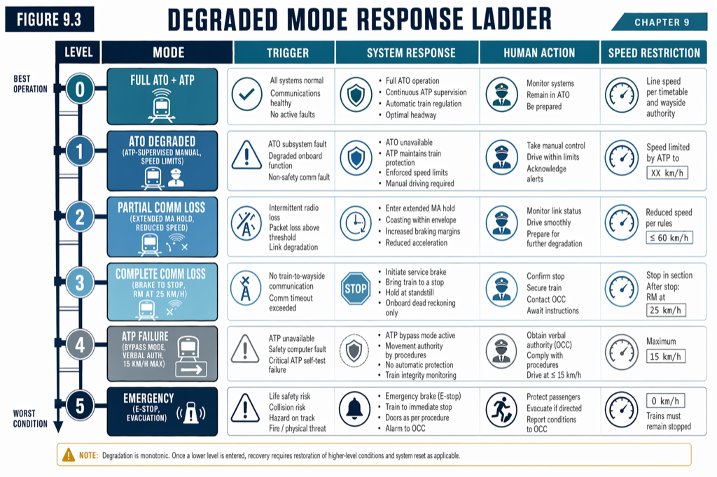 The degraded-mode ladder. Each rung defines a trigger, a behavior, and a recovery path; designing the ladder is the operational core of CBTC procurement.
Rung 4: Non-CBTC bypass
When ATP itself becomes unavailable across a corridor, the system steps to bypass mode. The trigger is a fault that takes the safety-critical layer offline: a sustained Zone Controller failure that exhausts both primary and standby, a confirmed ATP integrity fault on a critical wayside subsystem, or sustained loss of the Data Communication System beyond the recovery window (typically 30 minutes to 2 hours depending on operating rules).
On overlay deployments, the legacy fixed-block signaling layer takes over. Trains operate under wayside signal aspects, headways open from 2 to 3 minutes to 5 to 6 minutes, revenue speed drops to whatever the legacy signaling allows (40 mph on the L Line in bypass), and capacity falls 35 to 60 percent. On standalone deployments without retained legacy signaling, bypass collapses to dispatcher voice authority with yard-style speed limits (15 to 25 mph) and capacity reductions of 60 to 80 percent. The choice between overlay and standalone deployment, made years before the first revenue train, is what determines how survivable this rung actually is.
Recovery from bypass is the slowest of the rungs. Returning a corridor to CBTC operation requires resolving the underlying fault, validating the wayside subsystems against the recovered system, and re-establishing trains one at a time on the Zone Controller. Mature operators report bypass-mode dwell times of hours rather than minutes for any non-trivial cause, which is why bypass-mode design is one of the highest-leverage decisions in the procurement.
Rung 5: Withdrawn Service
The last rung is reserved for trains that cannot remain in revenue service even at degraded performance. A confirmed brake fault, a confirmed VOBC ATP fault, a door interlock failure that cannot be cleared, or a confirmed loss of position localization beyond dead-reckoning recovery all force the train out of any safe operating envelope. The system response is structured: brake the train to a controlled stop, evacuate passengers to the nearest safe location under attendant or operator supervision and OCC coordination, move the train out of the revenue corridor under tow or under heavily restricted manual control with maintenance escort, and absorb the capacity hit in downstream service while the failed train is cleared.
A line-wide Withdrawn Service event is the worst credible operational scenario short of an actual collision. It is rare on a mature deployment, but the procurement has to specify how it is handled because the safety case has to prove that even this scenario does not introduce new hazards — that the brake-to-stop is controlled, that the evacuation path is safe, that the recovery move does not collide with downstream traffic. (For the central CBTC architecture context that defines what each subsystem owns at each rung, see What Is a Zone Controller? CBTC’s Wayside Brain Explained.)
Designing the ladder in the RFP
The ladder is operationally invisible when it is well-designed and operationally catastrophic when it is not. Specifying it in the RFP requires four explicit decisions.
First, the redundancy posture for each Zone Controller. Hot-standby at every primary site is the default in modern US procurements, but the cost is real and some agencies specify cold or warm standby at less critical zones. The trade-off is recovery time: hot is sub-second, warm is seconds to a minute, cold is minutes. The right choice depends on the corridor’s headway, peak ridership, and the agency’s tolerance for a zone-wide service interruption.
Second, the deployment topology — overlay or standalone. Overlay retains legacy signaling beneath the CBTC layer and provides a usable bypass mode at 5- to 6-minute headway. Standalone removes the legacy signaling and depends on dispatcher voice authority for bypass, which is operationally expensive. Most US retrofits are overlay for exactly this reason; greenfield greenfield deployments are sometimes standalone if the regulatory and operational case supports it.
Third, the recovery time targets at each rung, in writing, with measurement methodology. Communication loss under 5 minutes, Zone Controller automatic failover under 1 minute, Zone Controller manual restart under 30 minutes, single-train RM clearing under 60 minutes, track circuit failure clearing under 2 hours. Without contractual targets, every recovery becomes a discussion rather than a deliverable.
Fourth, the diagnostic and maintenance interface. Every fault should produce a structured event log with fault code, timestamp, affected subsystem, and equipment state snapshot at the moment of failure. A degraded-mode ladder without diagnostics is a ladder maintenance cannot climb back up.
What this means in practice
- The degraded-mode ladder is the structured set of operating states between Normal and Withdrawn Service. Five rungs: hot-standby failover, single-train RM, zone-wide RM, Non-CBTC bypass, and Withdrawn Service.
- Most faults are absorbed at the top two rungs and are invisible to passengers. Hot-standby Zone Controllers and overlapping radio coverage are the procurement decisions that make this true.
- Single-train RM accounts for the bulk of operational degradation activity (about 70 percent of L Line RM events). Recovery is fast because only one train is affected; the rest of the line continues Normal-mode operation.
- Zone-wide RM and Non-CBTC bypass are the corridor-level rungs. Capacity impact is meaningful (20 to 60 percent depending on rung), and recovery time is measured in minutes to hours depending on the underlying fault and the procurement choices made earlier.
- Specify the ladder in the RFP. Redundancy posture, deployment topology, recovery time targets, and diagnostic interface should all be contractual, not vendor-discretionary.
Where to go next
This post is an 11-minute summary. The full treatment lives in Chapter 9 of Communications-Based Train Control (Volume 2): Buy on Amazon · Download Chapter 9 slides (free PDF)
Sources
- Wang, C. (2026). Communications-Based Train Control, Volume 2: Operations, Lifecycle, and US Deployment. Independent. ISBN 979-8-258-54295-3. — Chapter 9, “Operating Modes and Mode Transitions”; Chapter 5, “Wayside Equipment.”
- IEEE Standards Association. IEEE Std 1474.1: Standard for Communications-Based Train Control (CBTC) Performance and Functional Requirements.
- IEEE Standards Association. IEEE Std 1474.4: Recommended Practice for Functional Testing of a CBTC System.
- CENELEC. EN 50126: Railway Applications — RAMS.
- International Electrotechnical Commission. IEC 61508: Functional Safety.
- MTA New York City Transit. L Line CBTC Operational Reports. new.mta.info
- BART. Train Control Modernization Program — System Requirements. bart.gov/about/projects/tcmp
How this article was produced. Drafted with AI assistance, then reviewed and fact-checked by Chunjun (Francisco) Wang against Communications-Based Train Control (the author's two-volume reference) and primary sources — agency records, vendor documentation, and IEEE/IEC standards. Every date, vendor, and figure is traceable to a cited source. Spot a mistake? Corrections are welcome via the contact page.
Read the full treatment in the book
Chapter 9 of Communications-Based Train Control, Volume 2, covers this in depth.