technical · Article
End-to-End Latency in CBTC: Where the Milliseconds Go
A Communications-Based Train Control (CBTC) system has a single dominant timing parameter: the round-trip latency of the Movement Authority loop. A train reports its position; the wayside Zone Controller (ZC) computes a new MA accounting for that position; the new MA reaches the train and is acted upon. The total round-trip in a modern CBTC deployment runs 1.5 to 3 seconds, with the great majority of that budget consumed by a small number of identifiable phases. The latency is not a free parameter — every millisecond compresses against headway capacity, against safety-margin requirements, and against the reaction time available before a fault becomes a service incident. This article walks through the latency budget phase by phase, identifies which phases are physically bounded and which are engineering choices, and explains where a 30 percent improvement in any single phase translates into roughly 10 percent of headway recovered on a busy line.
Why the latency budget deserves its own engineering treatment
Latency is the parameter that ties together the technical chapters of any CBTC engineering review. The braking-curve safety margin (covered in Inside the CBTC Braking Curve: How Safe Stopping Distance Is Calculated) reserves distance for the round-trip latency at line speed: at 80 km/h, a 2-second total reaction time consumes 44 meters of stopping distance. The headway floor that determines line capacity (covered in How CBTC Lets the L Line Run a Train Every 110 Seconds, referenced in the cluster ① queue) is 30 to 40 percent latency, with the remainder absorbed by station dwell, MA-update cycles, and operational margin. The communication-loss timeout that triggers safe-state intervention (typically 250 milliseconds at the radio layer, 3 to 5 seconds at the application layer) is set with explicit knowledge of the typical round-trip latency.
A systems engineer reviewing a CBTC bid who can read the supplier’s latency budget — phase by phase, with numbers and the assumptions behind them — has the leverage to challenge headway claims, capacity projections, and safety-margin assertions. A reviewer who treats latency as a vendor-quoted aggregate accepts whatever the supplier asserts.
This article is for that reviewer.
The seven phases of the round-trip
A canonical Movement Authority round-trip decomposes into seven phases. The numbers below are representative ranges for a modern Wi-Fi-based CBTC deployment with hot-standby ZCs and dual-radio onboard units; specific deployments vary inside the ranges.
Phase 1: Onboard sensor fusion and position estimation (5 to 15 ms)
The Vehicle On-Board Controller (VOBC) reads tachometers, Doppler radar, accelerometer, and the most recent balise read; runs the sensor-fusion algorithm to produce the best-estimate position with associated uncertainty; assembles the position-report message. The phase is hard-bounded by the VOBC cycle time, which is typically 50 to 100 milliseconds (covered in The Onboard Side of CBTC: Inside the VOBC). The position-report assembly itself is a small fraction of one cycle.
This phase is essentially fixed by the onboard hardware. Compressing it requires faster sensors and faster processors, which the SIL 4 certification process resists. Modern VOBCs hover at the lower end of the range; not much budget is available here.
Phase 2: Radio uplink to access point (5 to 50 ms)
The position-report message traverses the wireless link from the train’s onboard radio to the nearest wayside access point (AP). The 5 to 50 ms range reflects the variability of Wi-Fi performance: a clear cell with light contention transmits in 5 to 10 ms; a contested cell with high passenger Wi-Fi load on adjacent channels can spike to 50 ms during peak crowding. Radio handover events during a moving train’s transit between cells add 100 to 150 ms when they occur (covered in Wayside Equipment Layout: Antennas, Cabinets, and Cable Routes).
This phase is the largest single source of latency variance in the round-trip. The mean is small; the tail is bad. CBTC engineers manage the variance by bounding the AP load (no more than two or three simultaneous train associations per AP), by using fast-roaming techniques (IEEE 802.11r) to keep handover under 150 ms, and by isolating CBTC traffic from passenger Wi-Fi (separate VLANs, separate access points where economically feasible). A line that has done this engineering well sees the radio uplink phase consistently under 20 ms; a line that has not sees occasional spikes that drive the round-trip over the typical envelope.
Phase 3: Backbone transit from AP to Zone Controller (5 to 30 ms)
The position-report message traverses the wired backbone from the AP to the ZC. On a self-healing fiber ring with PRP/HSR redundancy, the typical transit is 5 to 10 ms across two or three switch hops. On a longer or more congested backbone, 20 to 30 ms is plausible. The phase is bounded by switch latency, fiber propagation (5 microseconds per kilometer of fiber), and any encryption/decryption overhead at security gateways.
This phase is the most reliably low-variance contributor to the budget. Modern switched fiber backbones deliver this kind of latency comfortably. The compression headroom is small.
Phase 4: Zone Controller compute (200 to 500 ms)
The ZC runs its update cycle. The position report is one input; the ZC’s complete cycle includes inputs from all trains in its territory, all interlocking status, all alarms, and all ATS commands. The compute phase calculates safe-spacing windows for every train, generates Movement Authorities for every train, and produces the output set. The 200 to 500 ms range reflects the complexity: a ZC managing 5 trains in a zone runs cleanly at the lower end; a ZC managing 20 trains during peak runs nearer the upper end.
This phase is a significant fraction of the total round-trip and is the phase most often identified as compressible by vendors who promise “next-generation” performance. The compression strategy is more compute power and more efficient algorithms — both feasible, both bounded by the SIL 4 certification cost of replacing the ZC software stack. Most US deployments accept the 200 to 500 ms ZC compute window as the working number.
Phase 5: Backbone transit from ZC to AP (5 to 30 ms)
Symmetric to phase 3. The MA message traverses the backbone in the opposite direction. The latency profile is similar.
Phase 6: Radio downlink from AP to onboard radio (5 to 50 ms)
Symmetric to phase 2. The MA message reaches the train via the wireless link. The same variance considerations apply: clean cell, light contention, fast on average; contested cell or handover event, longer in the tail.
Phase 7: Onboard MA validation and acceptance (5 to 20 ms)
The VOBC receives the MA message; validates the EN 50159 message-layer protections (sequence number, timestamp, MAC, CRC); checks the MA against trajectory plausibility; updates the active MA used by the ATP envelope calculation. The phase is bounded by the VOBC cycle time and is essentially fixed.
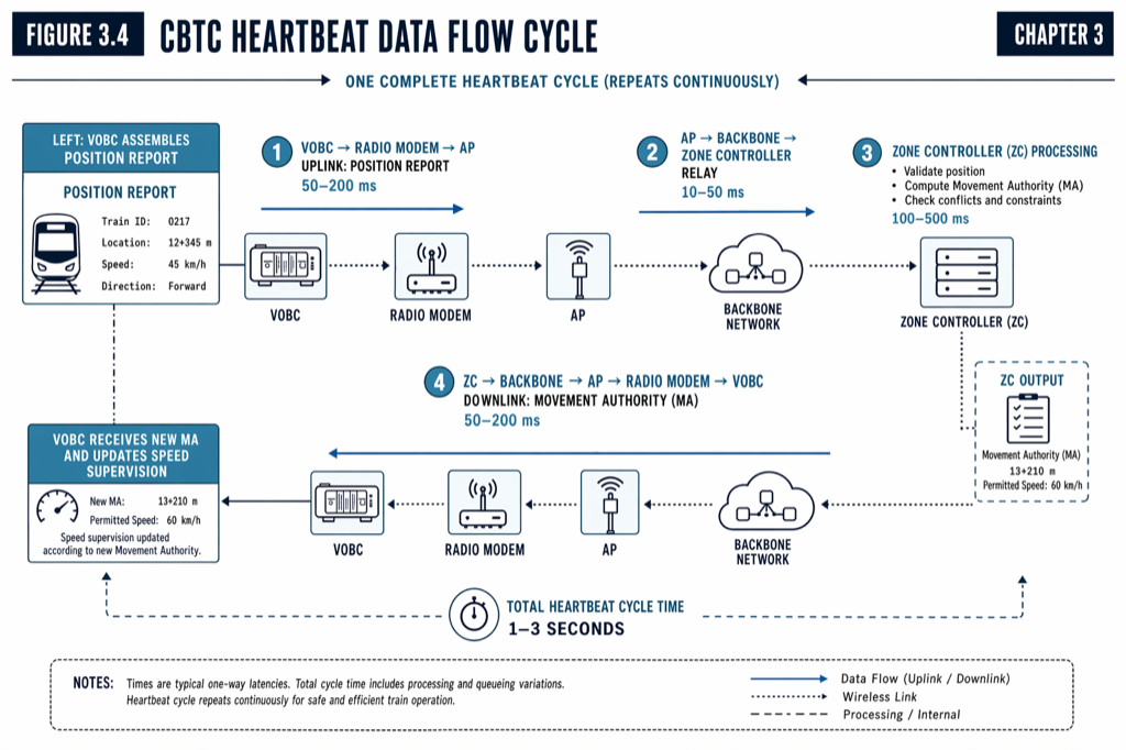 The round-trip is dominated by ZC compute (200 to 500 ms) and the radio variance at peak (5 to 50 ms each direction). Backbone and onboard phases are fast and stable.
The typical numbers, summed up
A representative latency budget for a healthy CBTC deployment under nominal conditions:
| Phase | Typical (ms) | Worst case (ms) |
|---|---|---|
| 1. Onboard fusion | 10 | 15 |
| 2. Radio uplink | 15 | 50 |
| 3. Backbone uplink | 8 | 30 |
| 4. ZC compute | 300 | 500 |
| 5. Backbone downlink | 8 | 30 |
| 6. Radio downlink | 15 | 50 |
| 7. Onboard validation | 10 | 20 |
| Round-trip total | 366 | 695 |
The typical round-trip in this budget is about 370 ms. The MA refresh interval in most deployments runs at 1 to 3 seconds because the MA is regenerated periodically rather than synchronously to position reports — the application-layer cycle is decoupled from the message-transit latency. The end-to-end loop from “train moves” to “train acts on updated MA reflecting that move” is therefore typically the MA refresh interval (1 to 3 seconds) plus the round-trip latency (about 370 ms typical), or roughly 1.4 to 3.4 seconds.
What the safety case actually budgets
The safety case does not budget the typical round-trip; it budgets the worst case. A MA computed against a position report that is 700 ms stale is the worst-case input to the safety logic; the braking-curve calculation reserves distance for that staleness as part of the position-uncertainty band.
The communication-loss timeout (typically 3 to 5 seconds at the application layer) also rests on the typical round-trip envelope. A CBTC system that loses communication does not panic until the timeout expires; the timeout is sized to permit a few missed update cycles without triggering safe-state intervention, but not so many that the train’s stale MA exhausts the safe distance margin.
The interesting boundary is the radio-layer timeout — typically 250 ms — that triggers fast-roaming or radio-failover before the application-layer timeout fires. This 250 ms is the budget for radio handover. A handover that runs to 200 to 250 ms is uncomfortably close to the limit; a handover that consistently runs at 100 to 150 ms leaves working margin. The fast-roaming engineering described in earlier sections is what keeps the handover phase under the deadline.
What is and is not compressible
The compressible phases of the round-trip are radio (phases 2 and 6) and ZC compute (phase 4). The radio phase is compressed by RF engineering — denser AP spacing, better antennas, isolated VLANs, fast-roaming protocols. The ZC compute phase is compressed by faster hardware and more efficient algorithms.
The non-compressible phases are onboard fusion and validation (phases 1 and 7) and the backbone transit phases (3 and 5). The onboard phases are bounded by the SIL 4 cycle time; the backbone phases are bounded by switch latency and fiber propagation, both of which are already small.
A vendor that proposes to halve the round-trip latency is implicitly proposing aggressive compression of phases 2, 4, and 6. The agency’s review should ask which specific compression strategy is being applied and what the cost is in terms of equipment, certification, or operational complexity. A vendor that cannot answer this question concretely is selling a brochure number.
The architectural alternatives that change the equation
Two architectural changes can reduce the round-trip latency by altering the topology rather than compressing the existing phases.
The first is distributed safety processing in onboard equipment, where some safety functions previously computed in the ZC migrate to the VOBC. A train that computes its own safe-distance-to-the-train-ahead — given broadcasts of neighbors’ positions and intents — is the train-to-train architecture discussed in Train-to-Train Communication: The Future or a Fantasy?. The latency saving is a half-round-trip, roughly 200 to 350 ms; the safety-case cost is substantial.
The second is edge-compute Zone Controllers, where the ZC moves from a central equipment room to a distributed edge in the network closer to the access points. The latency saving is the backbone transit (phases 3 and 5), about 10 to 60 ms in the worst case. The architectural cost is more equipment rooms with associated civil works, HVAC, and security. Few US deployments have justified this investment so far; the saved latency is small relative to the ZC compute phase that remains.
Practical takeaways
- The Movement Authority round-trip in a healthy CBTC deployment runs 370 ms typical, 700 ms worst-case, with the majority consumed by ZC compute (200 to 500 ms) and radio variance at peak (5 to 50 ms per direction).
- The MA refresh interval (1 to 3 seconds) is decoupled from the round-trip latency; the end-to-end position-to-MA-acting loop is typically 1.4 to 3.4 seconds.
- The radio phases are the largest source of latency variance. Tail-control engineering — AP load discipline, fast-roaming, VLAN isolation, dual radios — keeps the tail under the 250 ms radio-layer timeout that triggers fast-roaming and radio-failover.
- The compressible phases are radio (phases 2 and 6) and ZC compute (phase 4). Onboard and backbone phases are essentially fixed by certification, hardware, and physics.
- A vendor that promises a much-lower round-trip should be asked which specific phases are being compressed and what the trade-off is in equipment, certification, or operational complexity. Vague compression claims do not survive engineering review.
- Architectural alternatives (train-to-train, edge-compute ZC) change the latency equation rather than compress the existing budget. They have substantial safety-case and infrastructure costs that often exceed the latency savings.
Where to go next
This post is an 11-minute summary. The full treatment of CBTC architecture, communication systems, and timing budgets lives in Chapters 3 and 6 of Communications-Based Train Control (Volume 1 on Amazon). Download Chapter 3 slides (free PDF) and Chapter 6 slides.
For the Movement Authority concept that the round-trip generates, see The Movement Authority Concept: How a CBTC Train Decides How Far to Go. For the onboard cycle that bounds the onboard phases, see The Onboard Side of CBTC: Inside the VOBC. For the heartbeat-cycle context that sets the safety-state timeouts, see The Heartbeat Cycle: 200 ms That Keep Modern Metros Safe.
Sources
- Wang, C. (2026). Communications-Based Train Control, Volume 1: Foundations & Technical Architecture. Independent. ISBN 979-8-258-54295-3. — Chapter 3, “CBTC System Architecture Overview”; Chapter 4, “Onboard Equipment”; Chapter 5, “Wayside Equipment”; Chapter 6, “Communication Systems.”
- IEEE Standards Association. IEEE Std 1474.1: Communications-Based Train Control (CBTC) Performance and Functional Requirements.
- IEEE Standards Association. IEEE Std 802.11r: Fast Basic Service Set (BSS) Transition.
- CENELEC. EN 50159: Railway applications — Communication, signalling and processing systems — Safety-related communication in transmission systems.
- International Electrotechnical Commission. IEC 61375: Electronic railway equipment — Train communication network (TCN).
- International Electrotechnical Commission. IEC 62439-3: Industrial communication networks — High availability automation networks — Part 3: Parallel Redundancy Protocol (PRP) and High-availability Seamless Redundancy (HSR).
- Federal Transit Administration. State Safety Oversight Program. transit.dot.gov/regulations-and-guidance/safety/state-safety-oversight
- MTA New York City Transit. Communications-Based Train Control Status Update. new.mta.info/project/communications-based-train-control-cbtc
How this article was produced. Drafted with AI assistance, then reviewed and fact-checked by Chunjun (Francisco) Wang against Communications-Based Train Control (the author's two-volume reference) and primary sources — agency records, vendor documentation, and IEEE/IEC standards. Every date, vendor, and figure is traceable to a cited source. Spot a mistake? Corrections are welcome via the contact page.
Read the full treatment in the book
Chapter 3 of Communications-Based Train Control, Volume 1, covers this in depth.