definitional · Article
The Onboard Side of CBTC: Inside the VOBC
When the MTA awarded the L Line CBTC contract in 1999, one of the unspoken commitments inside the scope was that every R143 and later R160 train operating on the line would carry a fundamentally new piece of safety-critical equipment under its floor pan: the Vehicle On-Board Controller. Twenty-six years later, the original VOBC fleet has been through a mid-life refresh, the platform has evolved from PowerPC to ARM-class processors, and the same architectural pattern — redundant SIL 4 onboard computer, deterministic real-time cycle, sensor fusion, vital interface to traction and brake — defines every CBTC fleet in revenue service worldwide. The VOBC is the onboard counterpart to the wayside Zone Controller and the place where most of a CBTC retrofit’s cost-per-train lives. This post explains what is inside a VOBC, how it operates cycle by cycle, and what an agency should specify when ordering one.
Why the VOBC matters in procurement
For a transit agency planning a CBTC retrofit, the VOBC is typically the second-largest line item after wayside infrastructure. A new metro VOBC suitable for a SIL 4 deployment, with redundant safety processors, radio modem, sensor interfaces, and integration with traction and brake, costs roughly $200,000 to $400,000 per train at recent US procurement reference points. A 100-train fleet retrofit therefore commits $20 to $40 million in onboard hardware alone, before integration, testing, and rolling-stock modification labor. Underspecifying the VOBC produces a cheaper bid that fails integration testing; overspecifying it produces an unaffordable bid that wins the technical evaluation and loses the cost evaluation. This post is for the engineer or procurement specialist who needs to understand what the dial settings actually are.
The hardware: redundancy is the architecture
Every VOBC is built around redundant safety processors. The two common configurations are 2-out-of-2 (2oo2) and 2-out-of-3 (2oo3). In 2oo2, two independent processors run identical safety software in parallel; their outputs are compared every cycle, and disagreement triggers a safe-state transition (typically service brake plus diagnostic alarm). 2oo2 detects faults but does not tolerate them: a single processor failure forces a safe shutdown. In 2oo3, three independent processors vote, and the majority result wins. 2oo3 tolerates a single processor fault and continues operation; the cost is roughly 1.5 times the 2oo2 hardware count.
Most US metro deployments specify 2oo3 because metro service availability targets (commonly 99.5 to 99.9 percent) cannot tolerate single-fault shutdowns during peak operation. Some lighter-rail and APM deployments use 2oo2 with higher acceptance of service interruption.
Each processor in the VOBC redundancy set is a hardened embedded computer running at modest clock speed (typically 1 to 2 GHz, often ARM-architecture in modern designs, with PowerPC still present in legacy fleets). Memory is ECC-protected RAM, typically 4 to 8 GB, with 2 to 4 GB of nonvolatile flash for software and event logging. The operating system is a real-time kernel — INTEGRITY, QNX Neutrino, or VxWorks are common — not a general-purpose OS. The deterministic scheduling and bounded interrupt latency a real-time kernel provides are non-negotiable for safety-critical cyclic execution.
The VOBC enclosure is engineered for the rolling-stock environment. Vibration from wheelsets and traction equipment, temperature swings from -25 degrees Celsius (winter outdoor storage in the Northeast) to +55 degrees Celsius (sun-baked roof in Phoenix), moisture intrusion from track spray, and electromagnetic interference from traction inverters all impose specific test requirements. The relevant standards are IEC 61373 for shock and vibration, EN 61000-6-2 for electromagnetic immunity, and IP54 or IP65 enclosure ratings for moisture and dust. A VOBC that passes a benchtop demo but fails a winter season in Boston is not a delivered VOBC.
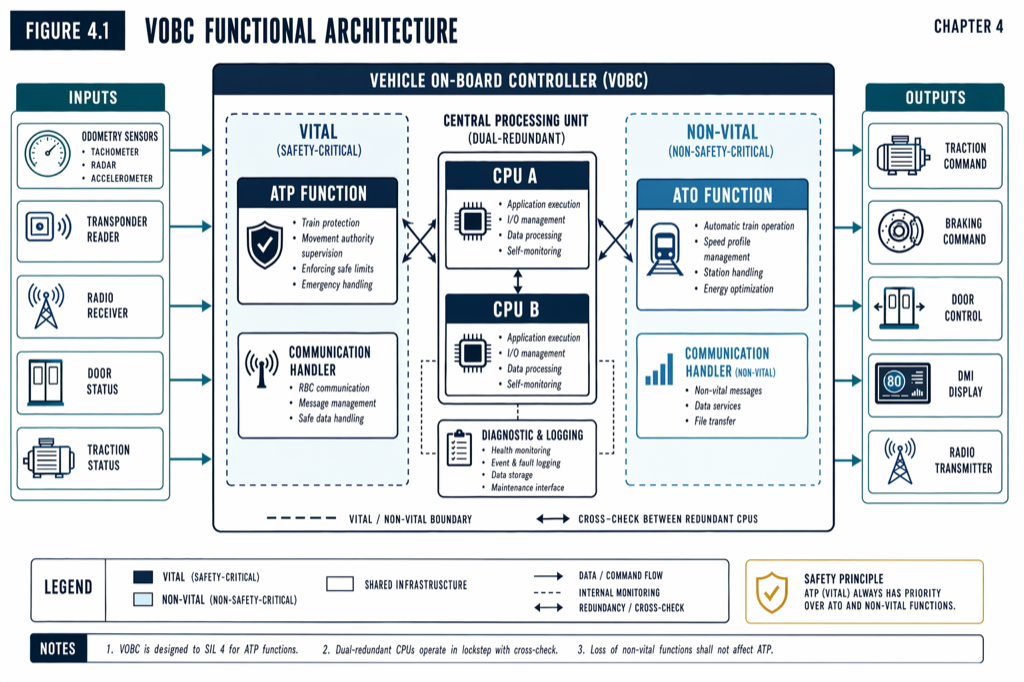 VOBC architecture: redundant safety processors run diverse implementations of identical ATP logic; a separate application processor handles non-safety ATO and TMS functions.
The cycle: what happens every 50 milliseconds
A VOBC operates on a fixed cycle, typically 50 to 100 milliseconds. Every cycle, the same sequence executes. Understanding this cycle is the cleanest way to understand what the VOBC actually does.
In the first phase (roughly 5 milliseconds), the VOBC ingests inputs. It reads sensor data from tachometers, Doppler radar, balise antenna, accelerometer, and door, brake, and traction status switches. It receives messages from the Data Communication System radio and from the Train Management System bus. Each input is range-checked, plausibility-checked against rate-of-change limits, and cross-checked against redundant sources where available. Inputs that fail validation are flagged; persistent failures trigger fault handling.
In the second phase (roughly 40 milliseconds), the VOBC computes. The redundant safety processors execute the ATP logic: parse and validate the most recent Movement Authority, compute the current speed envelope from current position to end-of-authority, compare actual speed against the envelope, and decide whether intervention is required. In parallel, the application processor computes ATO commands: target speed for the current segment, traction effort, braking effort, station-stopping profile.
In the third phase (roughly 5 milliseconds), the VOBC votes or compares. In 2oo3 voting, the majority of channel outputs wins. In 2oo2 comparison, the two channels must match within tolerance; mismatch triggers service brake. The voting logic is hardware, not software; the architecture refuses to trust software to validate software.
In the fourth phase (roughly 5 milliseconds), the VOBC outputs. Brake commands, traction commands, door enable signals, and DMI (Driver Machine Interface) updates are issued. The position uplink to the wayside Zone Controller is queued for the next radio transmit window.
The full cycle completes in 50 milliseconds. If any phase overruns its budget, a watchdog timer detects the overrun and forces a safe-state transition. The watchdog is hardware; it cannot be disabled by software fault. (For how the wayside uses the position uplink the VOBC sends, see The Movement Authority Concept: How a CBTC Train Decides How Far to Go.)
The sensor stack
Each VOBC integrates a small set of sensors that together provide the train’s continuous knowledge of its own position and motion.
Tachometers, mounted on non-driven axles, produce pulses proportional to wheel rotation. Most metro fleets carry two to four tachometers per train (one per bogie). The VOBC integrates pulses to relative distance and cross-checks tachometers against each other to detect slip and slide.
A Doppler radar mounted under the train measures ground speed independently of wheel rotation, providing the cross-check that catches tachometer error from wheel slip. Typical accuracy is around 0.2 m/s integrated to position over distance.
A balise antenna, mounted under the train’s leading axle, reads passive transponders embedded in the trackbed at known positions. Each balise read provides an absolute position reset; between reads, the VOBC dead-reckons from tachometer-Doppler fusion. Balises are spaced 200 to 500 meters apart on CBTC territory.
An accelerometer (MEMS, three-axis) provides longitudinal acceleration data for diagnostics and for cross-validation of tachometer-Doppler agreement during transients.
The fusion of these sensors is the heart of CBTC localization. (For the full localization picture, see How CBTC Trains Know Where They Are (Without Track Circuits).) The VOBC’s role is to run the fusion algorithm, report best-estimate position with associated uncertainty to the wayside, and continuously detect and respond to sensor faults.
The interfaces: where retrofit complexity lives
A VOBC is not a self-contained box; it is the central node of a small network of vital and non-vital interfaces with the train’s existing systems. The interfaces are where retrofit projects spend most of their integration effort.
The traction interface tells the propulsion system how much power to deliver. On modern AC-motor trains, this is typically a CAN-bus or hardwired analog command to the traction inverter. On legacy DC-motor trains, the interface may require a custom adapter. The retrofit complexity depends entirely on what the existing traction system was designed to accept.
The brake interface commands service brake, emergency brake, and brake-pressure feedback. Pneumatic brake systems require analog pressure command and feedback; electrohydraulic systems use digital interfaces. The interface must be vital — failure of the VOBC must default to brake application, not brake release.
The door interface enables and inhibits door opening. The VOBC must inhibit doors while the train is moving and enable doors only when the train is stopped at a designated platform. Door fault detection is a leading source of in-service incidents on CBTC lines; many failure modes that look like signaling issues are actually door interface issues.
The TMS (Train Management System) interface is non-vital and carries diagnostic, maintenance, and passenger information data over MVB (Multifunction Vehicle Bus) on European designs or Ethernet on newer ones.
The DMI (Driver Machine Interface) is the cab display showing speed, target speed, MA boundary, system health, and fault alarms. On manually driven CBTC at GoA 1 or GoA 2, the DMI is the operator’s primary situational awareness; its design and ergonomics have direct safety implications. (For the GoA framework, see Chapter 8 of the manuscript.)
Mid-life refresh: the conversation no one wants to have
VOBC hardware is engineered for a 20- to 25-year service life, matching the rolling-stock platform. But processor technology, memory standards, and communication protocols evolve faster than that. A VOBC deployed in 2009 with PowerPC processors, MVB fieldbus, and 512 MB of memory is severely constrained against 2026 standards.
The accepted industry pattern is a mid-life technology refresh at year 10 to 12 of service: replace processor boards with newer designs maintaining the same form factor and interface, upgrade software to take advantage of new capabilities while preserving API compatibility, refresh power supplies and cooling, and re-certify the safety case for the refreshed platform. Industry references put the cost of mid-life refresh at roughly 30 to 50 percent of the original VOBC cost, and the refresh extends service life by another 10 to 12 years.
Agencies that procure CBTC and do not budget for mid-life refresh produce a 25-year cost picture that looks better than the actual lifecycle cost. Specifying a clean refresh path in the original RFP — including supplier obligations to provide compatible hardware in year 10 to 12 — is one of the highest-leverage decisions an agency makes during procurement.
Practical takeaways
- A VOBC is a redundant SIL 4 onboard safety computer. Most US metro deployments specify 2-out-of-3 voting for service-availability reasons.
- The cycle time is the architectural metronome. 50 to 100 ms is typical; the VOBC must complete input, compute, vote, and output every cycle without exception.
- Sensor fusion (tachometer, Doppler, balise, accelerometer) is a core VOBC function. Specify sensor fault behavior in the RFP, not just nominal accuracy.
- Vital interfaces to traction, brake, and door are where retrofit projects spend integration time. Existing rolling-stock interface details determine VOBC design complexity more than any other factor.
- Mid-life refresh is real and is roughly 30 to 50 percent of original cost. Bake it into the lifecycle budget; require the supplier to commit to a refresh path.
Where to go next
This post is a brief overview. The full treatment lives in [Chapter 4 — Onboard Equipment] of Communications-Based Train Control (Volume 1 on Amazon). Download Chapter 4 slides (free PDF →)
Sources
- Wang, C. (2026). Communications-Based Train Control, Volume 1: Foundations & Technical Architecture. Independent. ISBN 979-8-258-54295-3. — Chapter 4, “Onboard Equipment.”
- IEEE Standards Association. IEEE Std 1474.1: Standard for Communications-Based Train Control (CBTC) Performance and Functional Requirements.
- International Electrotechnical Commission. IEC 61508: Functional Safety of Electrical/Electronic/Programmable Electronic Safety-related Systems.
- International Electrotechnical Commission. IEC 61373: Railway applications — Rolling stock equipment — Shock and vibration tests.
- CENELEC. EN 50128: Railway applications — Communication, signalling and processing systems — Software for railway control and protection systems.
- CENELEC. EN 50129: Railway applications — Safety related electronic systems for signalling.
- MTA New York City Transit. L Line CBTC Project Documentation. new.mta.info
- BART. Train Control Modernization Program. bart.gov/about/projects/tcmp
How this article was produced. Drafted with AI assistance, then reviewed and fact-checked by Chunjun (Francisco) Wang against Communications-Based Train Control (the author's two-volume reference) and primary sources — agency records, vendor documentation, and IEEE/IEC standards. Every date, vendor, and figure is traceable to a cited source. Spot a mistake? Corrections are welcome via the contact page.
Read the full treatment in the book
Chapter 4 of Communications-Based Train Control, Volume 1, covers this in depth.