comparative · Article
Radio-Based vs Inductive-Loop CBTC: When Each Wins

The first revenue-service Communications-Based Train Control (CBTC) systems in North America did not run on Wi-Fi. They ran on inductive loops: continuous wires laid along the track that radiated and received digital messages through the train’s pickup coils. Vancouver SkyTrain’s 1985 opening, Detroit People Mover, and the original San Francisco Muni Metro CITYFLO installation all used variants of inductive-loop train-to-wayside communication. The radio-based architecture that now dominates US procurement, anchored in IEEE 802.11 spread-spectrum radio, did not become the default until the 2000s. Twenty-five years later, the radio-based vs inductive-loop CBTC question is mostly settled in favor of radio. But “mostly settled” leaves a few corridors where inductive loops are still the right answer, and any agency writing a CBTC RFP should understand both architectures well enough to ask the right questions.
Why this comparison still matters
Three reasons keep the comparison alive in 2026. First, several US deployments still operate inductive-loop CBTC and will continue to do so for the remaining lifecycle of the asset. Replacement decisions on those lines need to be informed by what the original architecture actually delivered, not by a default assumption that radio is always superior. Second, inductive-loop technology is a known reference point in any RFP that asks vendors to demonstrate degraded-mode behavior, communication-loss resilience, and predictable RF performance; the architecture has different failure modes than IEEE 802.11 radio, and some of those modes are advantageous on specific corridors. Third, the emergence of LTE-R and private 5G as alternative radio options reopens the broader question of what the right wayside-to-train communications channel looks like for the next 30 years. Understanding the full design space, including inductive loops, sharpens that conversation.
How inductive-loop CBTC actually works
An inductive-loop CBTC system runs continuous twisted-pair cables along the track, typically embedded in the running rails or fastened to the underside of guideway structures. The wayside transmitter modulates the signal onto the loop; the train’s onboard antennas (mounted under the car) couple inductively to the loop and decode the message. The reverse path works similarly: the train transmits, the loop receives, and the wayside aggregates the data.
The architectural advantages flow from the constrained RF environment. Because the signal is inductively coupled into a defined loop, it is largely immune to interference from non-rail RF sources. Microwave ovens, passenger Wi-Fi, neighboring industrial equipment, and the broadband interference that plagues 2.4 GHz unlicensed deployments simply do not reach the inductive channel. The link budget is predictable; the coupling geometry is fixed; the signal-to-noise margin can be engineered with high confidence. For revenue-service operation, that predictability has tangible value.
The architectural disadvantages flow from the same constraint. The loop is physical infrastructure that must be installed, maintained, and protected from track work, broken bonds, and electrolytic corrosion. The data rate is low by modern standards (typically a few hundred kilobits per second versus the tens of megabits available from a 5 GHz Wi-Fi access point). Adding additional loop segments to extend coverage, increase capacity, or support new functionality is a civil-works project, not a software update. Cutover from one loop generation to another is similarly invasive. The capital cost per route-mile is higher than a comparable radio deployment, and the operational flexibility is lower.
 Inductive loops constrain the RF environment by physical geometry; radio-based CBTC constrains it by spectrum management.
How radio-based CBTC actually works
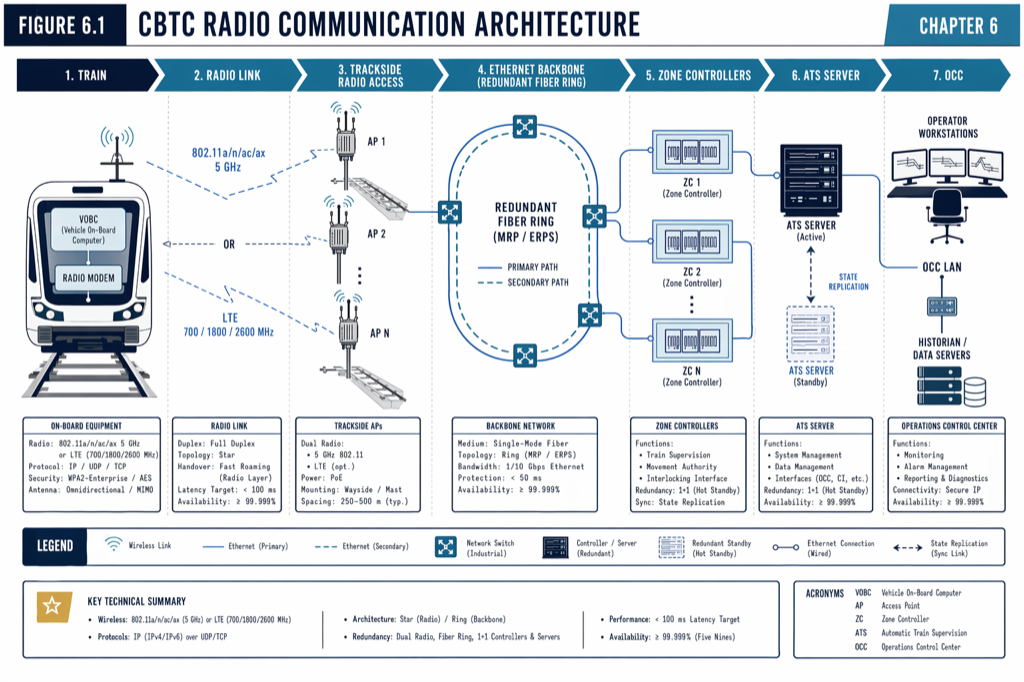
Radio-based CBTC uses spread-spectrum radio on standardized frequencies, typically the 2.4 GHz and 5 GHz unlicensed bands under IEEE 802.11. Wayside access points are spaced along the track at distances of 200 to 400 meters in tunnels and 300 to 500 meters in elevated or at-grade sections, with overlapping coverage zones to enable seamless handover. Trains carry redundant rooftop antennas connected to dual onboard radios. The physical layer is commercial off-the-shelf Wi-Fi technology, hardened for the rail environment but not fundamentally different from enterprise wireless infrastructure.
The architectural advantages are the inverse of inductive-loop’s disadvantages. Capital cost per route-mile is lower because the access points are commodity equipment and the cable infrastructure is conventional Ethernet plus power-over-Ethernet. Data rates are abundant; modern 802.11ac access points support hundreds of megabits per second per train, far in excess of CBTC’s actual bandwidth requirements (tens of kilobits per second per train for safety-critical traffic). Adding capacity or new applications is a software and configuration exercise, not a civil-works project. The integration with the agency’s broader IT infrastructure is straightforward.
The architectural disadvantages are the inverse of inductive-loop’s advantages. The 2.4 GHz band in particular is heavily contested with passenger devices, neighboring networks, and consumer Wi-Fi; modern deployments use 5 GHz as the primary CBTC channel for that reason. Even at 5 GHz, the unlicensed band is shared, and the agency cannot guarantee that no future regulatory or environmental change will impair link performance. Handover between access points must be engineered carefully (fast-roaming techniques, key caching, predictive handover orchestration) to meet the sub-250-millisecond CBTC handover deadline. Cybersecurity exposure is broader because the radio interface reaches further than any inductive-loop signal. (The DCS architecture is unpacked further in the future article on Wi-Fi vs LTE-R for Train-to-Wayside.)
Comparative behavior under fault
The most useful frame for comparing the two architectures is how each behaves under specific fault conditions, because that is where the procurement consequences live.
A broken or damaged inductive loop produces a sharply localized loss of communication; the train detects the fault when it enters the affected segment, reports the loss, and the wayside transitions the train to a defined degraded mode. Repair is invasive (track access, cable splicing, bond replacement) but the failure boundary is unambiguous. By contrast, RF interference in a radio-based deployment can produce intermittent communication loss across multiple access points, and diagnosing the root cause in real time is harder; the symptom is messy even when the underlying issue (a rogue access point, a passenger device, a defective vendor radio module) is fixable.
A radio access point failure produces a coverage gap whose impact depends on the overlap-coverage design. A well-engineered deployment with 30-to-50 percent overlap between adjacent APs continues to operate with one AP failed; the train hands over earlier or later than nominal but does not lose continuous communication. A deployment with marginal overlap can produce a service-affecting gap. The procurement specification should require demonstrated AP-failure tolerance, not just nominal handover times.
Cybersecurity threats favor inductive-loop architectures in one specific sense: an attacker outside the loop’s geometry cannot easily inject malicious traffic. An attacker with access to the access-point network or a malicious Wi-Fi device near the right-of-way has more options on a radio-based deployment. Defense-in-depth (network segmentation, encryption, authentication, continuous monitoring) closes most of the radio-architecture gaps, but the inductive-loop architecture has a structural advantage on this dimension that is worth acknowledging in the procurement decision.
Lifecycle cost: capital, operations, maintenance
The capital cost differential favors radio-based architectures. Inductive-loop installation requires substantial civil work, specialized cable, and longer commissioning. Radio-based installation is faster, cheaper, and less disruptive to existing service. For a typical 10-mile US metro line, the radio-based capital is in the manuscript-cited range of $15 to $25 million per 10 km; an equivalent inductive-loop deployment runs higher, particularly when the cable infrastructure must be installed in a brownfield environment.
Operational and maintenance costs are more nuanced. Radio-based deployments have more software and more configuration complexity, which translates to ongoing engineering effort to manage RF performance, security posture, and vendor patches. Inductive-loop deployments have less software but more civil-maintenance burden; broken bonds, cable degradation, and physical damage from track work all generate recurring repair costs. Over a 30-year lifecycle, radio-based architectures typically come out ahead, but the differential is smaller than the capital comparison suggests.
The replacement cost is where the architectural choice has its longest tail. Replacing a radio-based DCS at end-of-life is a network-equipment refresh; access points, switches, and onboard radios are replaced over a defined cutover window with manageable disruption. Replacing an inductive loop is a civil-works project that cannot be done without extensive track access. Agencies still operating inductive-loop CBTC must plan for that civil work in their capital programs; agencies considering inductive-loop deployments today should weight the replacement cost into the lifecycle analysis.
Where inductive-loop still wins
Despite the cost and flexibility advantages of radio-based architectures, three specific corridor profiles still favor inductive loops in 2026.
The first is the closed automated people mover with bounded geometry, predictable operating environment, and a strong preference for predictable RF behavior. JFK AirTrain (Bombardier, now Alstom Innovia, opened December 2003) and similar airport people movers operate in environments where the inductive-loop architecture’s interference immunity has tangible value. These systems are also typically GoA 4 (unattended) and benefit from the architecturally simpler safety case.
The second is high-RF-noise environments where unlicensed-band radio cannot reliably guarantee link availability. Heavy industrial corridors, certain port operations, and underground systems with extensive electrical infrastructure can produce interference profiles that radio-based CBTC must engineer around. An inductive-loop deployment may, in those environments, be the more conservative engineering choice.
The third is the legacy operator with substantial existing inductive-loop infrastructure and no immediate operational reason to migrate. Vancouver SkyTrain has run inductive-loop CBTC for four decades; continuing to invest in that architecture for parts of the network where the existing infrastructure is sound is rational, even as new lines are deployed on radio-based equipment.
| Aspect | Radio-Based CBTC | Inductive-Loop CBTC |
|---|---|---|
| Capital Cost | Lower | Higher |
| Operating Cost | Complex software management | Higher civil-maintenance burden |
| RF Tolerance | Shared spectrum, potential interference | Immune to non-rail RF interference |
| Scalability | Software and configuration updates | Civil-works project for expansion |
| Fault Behavior | Intermittent communication loss | Localized loss, clear failure boundary |
| Cybersecurity | Broader exposure | Structural advantage |
What this means in practice
- Default to radio-based CBTC for new procurement unless the corridor profile (closed APM, high-RF-noise environment, or substantial existing inductive-loop infrastructure) provides a specific reason to do otherwise.
- Specify access-point failure tolerance and demonstrated handover performance under fault conditions, not just nominal handover times. The performance under stress is where radio-based deployments earn or lose their reliability case.
- For agencies operating legacy inductive-loop CBTC, plan civil-works replacement cost into the 30-year capital program. The replacement of inductive infrastructure is more invasive than radio replacement.
- Treat the cybersecurity surface as a procurement-relevant axis. Radio-based deployments require defense-in-depth (segmentation, encryption, monitoring); inductive-loop deployments have a structurally smaller attack surface but cannot be assumed immune.
- A multi-architecture agency posture is defensible: inductive-loop on legacy lines, radio-based on new ones. Do not force uniformity for its own sake.
Where to go next
This post is a comparison overview. The full treatment of CBTC communication architectures, including network design, redundancy, and the path to LTE-R and 5G, lives in Chapter 6 (“Communication Systems”) and Chapter 15 (“Vendor Landscape and Technology Trends”) of Communications-Based Train Control (Volume 1 on Amazon). Download Chapter 6 slides (free PDF)
Sources
- Wang, C. (2026). Communications-Based Train Control, Volume 1: Foundations & Technical Architecture. Independent. ISBN 979-8-258-54295-3. — Chapter 6, “Communication Systems”; Chapter 15, “Vendor Landscape and Technology Trends.”
- IEEE Standards Association. IEEE Std 1474.2: Standard for Communications-Based Train Control (CBTC) Communication Requirements.
- IEEE Standards Association. IEEE 802.11 Wireless LAN Standards.
- Federal Communications Commission. Unlicensed National Information Infrastructure (U-NII) and Industrial, Scientific, and Medical (ISM) Band Rules. fcc.gov/general/wireless-services
- Transportation Security Administration. Surface Transportation Cybersecurity Directives 1580 and 1582. tsa.gov/foia/readingroom
- TransLink. SkyTrain System Information. translink.ca/about-us/about-translink/our-history
Read the full treatment in the book
Chapter 3 of Communications-Based Train Control, Volume 1, covers this in depth.