technical · Article
The Signaling Block Diagram: A Field Engineer's Reading Guide

A field engineer assigned to a Communications-Based Train Control (CBTC) project will, within the first week, be handed a stack of signaling block diagrams and expected to read them. The drawings are not new — every railroad has had block diagrams since the 1880s, and the conventional symbology has been essentially stable for half a century. What is new is the CBTC overlay: zone-controller territories, balise locations with telegram identifiers, access-point coverage, and the moving-block annotations that turn a fixed-block-era drawing into a usable CBTC reference. Reading these diagrams quickly and accurately is the difference between an engineer who contributes to a route walk-through and an engineer who slows it down. This article is the field engineer’s guide to the signaling block diagram circa 2026: what each symbol means, how the CBTC overlay sits on top of the legacy convention, and what to look for when the drawing and the field do not agree.
Why the block diagram is still the working drawing
Every CBTC project produces a stack of more elegant drawings: architectural diagrams of the network, three-tier physical-architecture views, vital/non-vital partition diagrams, message-sequence charts. None of these is the drawing the field engineer carries on a route walk. The drawing carried in the field is the signaling block diagram — a long, narrow, scaled drawing of the track with every signaling element annotated at its physical location. It is the drawing that tells you what to expect at each kilometer post, what a malfunction at a specific switch implies for the route, and where the boundary lies between zone controllers, between interlockings, and between operating modes.
The block diagram is the working drawing because it is the only drawing that ties symbol to physical location. Every other drawing is logical; only the block diagram is geographic. When a Zone Controller alarms, the dispatcher and the technician both reach for the block diagram first.
This article is for the field engineer, the operations technician on a route walk, the consultant attending a design review, or the new hire trying to understand what the senior engineer is gesturing at on the drawing.
The legacy convention: what was on the drawing before CBTC
Long before CBTC, US signaling block diagrams used a conventional symbology that has remained roughly stable. The drawing reads left-to-right or as a long strip aligned with a station’s milepost progression. Track is drawn as a horizontal line; switches are drawn at the milepost where they branch, with the switch number labeled below the symbol; signals are drawn above the track with their indication aspects color-coded; track circuits are drawn as labeled segments between insulated joints.
A typical legacy block-diagram annotation set includes:
- Track segments with their milepost designations and track-circuit identifiers (T-100, T-101, etc.)
- Switches with their numbers (W-12, W-13) and normal/reverse position indicators
- Wayside signals with their identifiers and aspect families (home signal, distant signal, dwarf, marker)
- Insulated joints marking the boundaries of track circuits
- Speed restrictions, both permanent (curves, special work) and temporary
- Crossings, level crossings, and grade crossings
- Station platforms with platform stopping marks
- Equipment rooms, relay shelters, and similar wayside infrastructure
The convention is dense. A drawing of a 5-kilometer line section is typically 1.5 to 3 meters long when printed at 1:1000 scale, and contains hundreds of distinct annotations. Reading it quickly is a learned skill.
What CBTC adds to the drawing
The CBTC overlay adds a parallel layer of annotation that does not displace the legacy convention but extends it. The new symbology includes:
Zone Controller territory boundaries. Each ZC’s territory is bounded by clearly marked boundary lines, typically with the ZC identifier (ZC-A, ZC-B) labeled in the territory. The handover zones at boundaries are usually annotated as 100- to 300-meter overlap regions where both ZCs may briefly hold authority.
Object Controller locations. Each OC cabinet is marked at its location — typically near the switches and signals it controls — with its identifier and the elements it serves.
Balise locations. Every balise (Eurobalise or proprietary beacon) is marked with its absolute milepost, its telegram identifier, and its track-identity tag. On a moving-block drawing, balise spacing is dense — typically 50 to 200 meters in open running and one or more per platform stopping mark — and the diagram becomes correspondingly busy.
Access-point locations. Each radio access point is marked at its physical position on the tunnel wall or trackside structure, with its identifier and its frequency channel allocation. The cell coverage overlap between adjacent APs is sometimes shaded as a band along the track.
Moving-block overlay. On overlay-CBTC lines (where legacy fixed-block signaling is retained beneath the CBTC), the moving-block layer is drawn as a parallel strip above or below the fixed-block strip. The fixed-block layer shows the conventional signal-aspect logic; the moving-block layer shows the CBTC train positions and Movement Authority extents. The two layers must be read together to understand the operational state.
ATS supervision boundaries. The line is divided into ATS supervision zones (which may or may not align with ZC zones), and the boundaries are annotated. Some installations also annotate which dispatcher position manages each zone during normal operations.
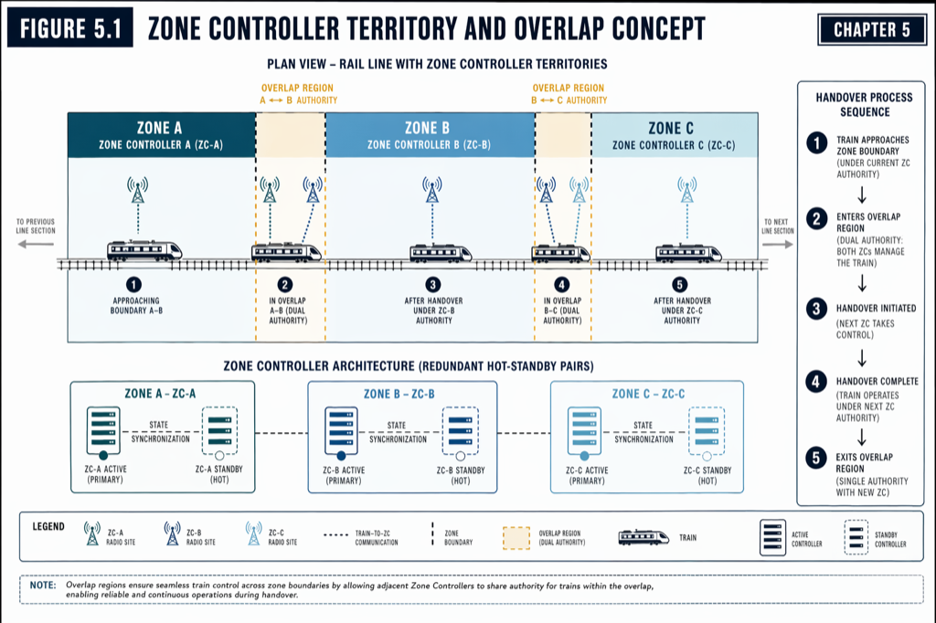 The CBTC overlay extends the legacy convention rather than replacing it. Reading a 2026 diagram requires reading both layers together.
The annotations that matter most for operational decisions
Several specific annotations carry disproportionate operational weight when reading a diagram in the field.
The handover zone width. ZC handover zones are typically 100 to 300 meters wide. A train that loses radio coverage inside the handover zone may be in either ZC’s territory; if the radio recovers, the recovery may be to the ZC the train left rather than the ZC it entered. The handover-zone annotation tells the technician where to look for ambiguous-state alarms.
The balise telegram database. Each balise carries an absolute position telegram. The drawing should annotate every balise’s telegram ID and expected location. A balise that has shifted by 20 millimeters from its surveyed position will pass commissioning but produce intermittent localization errors in service; the drawing’s expected positions are the reference for the survey-based fault investigation.
The access-point channel allocation. Adjacent APs on the same channel will produce co-channel interference where their coverage areas overlap. The diagram should annotate the channel for each AP and should make the channel-reuse pattern visible. A drawing that does not show channel allocation is missing the diagnostic information needed for an interference investigation.
The fixed-block signal aspects on overlay lines. On overlay-CBTC lines, the fixed-block aspects continue to govern non-CBTC and degraded-mode trains. The diagram must show the legacy signal aspects accurately; an inaccurate aspect annotation can mask a misoperation in degraded mode that the CBTC layer would otherwise have caught.
The mainline-yard boundary. Where the line meets a yard, the diagram should clearly mark the boundary, the mode-transition zone, and the boundary beacon location. (See CBTC in Storage Yards: Why It’s a Different Engineering Problem for why this boundary deserves engineering attention.)
Speed restrictions. Permanent speed restrictions (curve approach, station approach) and the points where temporary restrictions can be applied. Both must appear on the drawing because they govern the ATP envelope at each location (covered in Inside the CBTC Braking Curve: How Safe Stopping Distance Is Calculated).
When the drawing and the field disagree
A field engineer who walks the route eventually finds a place where the drawing and the field disagree. The most common discrepancies, in rough order of frequency:
A balise has been replaced and the new telegram does not match the drawing. Maintenance records get out of sync with the as-built drawing. The drawing shows balise B-103 with telegram 0x1234; the actual balise on track responds with 0x5678. This is a maintenance-records issue, not a safety issue; the train accepts the response and uses the position the telegram encodes regardless of what the drawing says.
An access point has been relocated. AP enclosures sometimes get moved during civil maintenance work. The drawing shows AP-22 at milepost 12.45; the AP is actually at 12.47. Two centimeters of drift do not matter; two meters do, because they shift the cell-edge location.
A switch has been removed or added. Usually during long-term capital projects. The drawing reflects the original design; the field reflects the most recent capital addition. Switch number sequencing and identifiers on the field cabinet are the authoritative reference.
A wayside signal has been masked or removed. Overlay-CBTC projects sometimes remove redundant aspects to simplify operations. The drawing must reflect the current state because the drawing governs the legacy fall-back operating procedure.
Equipment-room boundaries differ. The drawing shows the ZC equipment room at the south-end of the platform; the room is actually behind the back-of-house corridor. This kind of disagreement is unlikely to affect operations but matters for maintenance access procedures.
The reconciliation procedure is consistent: when drawing and field disagree, the field is the authoritative reference for the current configuration, and an as-built revision should be filed for the drawing. The engineer who is sloppy about filing reconciliation reports produces a drawing set that drifts from operational reality over the years and becomes useless for incident investigation.
What an RFP should specify about drawings
A CBTC procurement that wants to inherit a usable drawing set should require the supplier to deliver against four specific items.
Drawing convention specification. The agency should specify the symbol set, scale, layer organization, and file format for all signaling block diagrams. Vendor-specific conventions are usable but not transferable; an agency that specifies a documented standard is making the post-handover maintenance feasible.
As-built reconciliation procedure. The contract should require the supplier to deliver as-built drawings reconciled against the field at substantial completion, with explicit deltas from the design drawings called out.
Configuration management for drawings. Drawings change over the life of the system. The contract should require a drawing-change-control procedure that maintains the drawing set as a living document.
Drawing-database integration. Modern signaling drawings are not standalone PDFs; they are projections of a configuration database that holds the canonical state. The contract should require that the drawing database be deliverable, accessible, and editable by the agency post-handover. Without this, the agency becomes locked into the supplier for any future drawing revision.
Practical takeaways
- The signaling block diagram is the field engineer’s working drawing. It is the only drawing that ties signaling-element symbols to physical locations.
- The legacy block-diagram convention (track, switches, signals, track circuits, insulated joints, speed restrictions, platforms) remains the foundation. CBTC adds a parallel layer of annotation: ZC territories, OC locations, balise telegrams, AP locations and channels, moving-block overlays, and ATS supervision zones.
- Specific high-value annotations: ZC handover-zone width, balise telegram IDs, AP channel allocations, fixed-block signal aspects on overlay lines, mainline-yard boundary, and speed restrictions. These drive operational decisions and incident investigation.
- When drawing and field disagree, the field is authoritative. Filing as-built reconciliations is essential discipline; sloppy reconciliation produces a drawing set that becomes useless for incident analysis over years.
- A procurement should specify drawing convention, as-built reconciliation procedure, configuration management, and drawing-database deliverable accessibility. Without these, the agency inherits a drawing set that is hard to maintain and hard to extend.
Where to go next
This post is a 10-minute summary. The full treatment of CBTC architecture, wayside equipment, and the documentation deliverables that come with a CBTC project lives in Chapters 3, 5, and 12 of Communications-Based Train Control (Volume 1 on Amazon). Download the slides (free PDF).
For the Zone Controller territories the diagram annotates, see What Is a Zone Controller? CBTC’s Wayside Brain Explained. For the Movement Authority concept the moving-block overlay represents, see The Movement Authority Concept: How a CBTC Train Decides How Far to Go. For the wayside layout the access-point annotations describe, see Wayside Equipment Layout: Antennas, Cabinets, and Cable Routes.
Sources
- Wang, C. (2026). Communications-Based Train Control, Volume 1: Foundations & Technical Architecture. Independent. ISBN 979-8-258-54295-3. — Chapter 3, “CBTC System Architecture Overview”; Chapter 5, “Wayside Equipment.”
- IEEE Standards Association. IEEE Std 1474.1: Communications-Based Train Control (CBTC) Performance and Functional Requirements.
- American Railway Engineering and Maintenance-of-Way Association. AREMA Communications and Signals Manual. arema.org
- American Public Transportation Association. Standards for Rail Transit Engineering and Maintenance. apta.com/research-technical-resources/standards
- International Electrotechnical Commission. IEC 62290: Railway applications — Urban guided transport management and command/control systems.
- Federal Transit Administration. State Safety Oversight Program. transit.dot.gov/regulations-and-guidance/safety/state-safety-oversight
- MTA New York City Transit. Communications-Based Train Control Status Update. new.mta.info/project/communications-based-train-control-cbtc
How this article was produced. Drafted with AI assistance, then reviewed and fact-checked by Chunjun (Francisco) Wang against Communications-Based Train Control (the author's two-volume reference) and primary sources — agency records, vendor documentation, and IEEE/IEC standards. Every date, vendor, and figure is traceable to a cited source. Spot a mistake? Corrections are welcome via the contact page.
Read the full treatment in the book
Chapter 3 of Communications-Based Train Control, Volume 1, covers this in depth.