standards · Article
The V-Model Lifecycle for Safety-Critical Train Control

The V-model is sometimes dismissed as a 1990s artifact — heavyweight, sequential, incompatible with the agile cadence software engineers in other industries take for granted. In safety-critical rail signaling, that dismissal misreads what the V-model is actually for. CBTC projects routinely manage 500 to 1,500 system-level requirements, decomposing into 5,000 to 15,000 lower-level requirements across onboard, wayside, communication, and central subsystems. Every one of those requirements must trace to a verification activity. Every safety-critical function must be developed, reviewed, and validated under EN 50126, EN 50128, and EN 50129 lifecycle discipline. The V-model is the framework that makes this traceability auditable. When a CBTC project misses revenue service by twelve months, the cause is almost never a misunderstood agile sprint. It is a broken trace from a stakeholder requirement to a design decision to a test case.
Why this matters for procurement
The V-model is not just an engineering framework; it is the structural backbone of the safety case the agency will eventually present to its State Safety Oversight reviewer. An RFP that does not require V-model deliverables (Systems Engineering Management Plan, requirements traceability matrix, configuration management plan, validation and verification plan) is an RFP that has not asked the supplier for the documentation the SSO will demand. This post is for the program manager structuring the project schedule, the consulting engineer reviewing supplier proposals, and the agency systems engineer maintaining the requirements baseline.
The V-model framework
The V-model gets its name from its shape. The left descending arm is design decomposition: stakeholder requirements (what the agency needs the system to do) flow down into system-level requirements, then into subsystem requirements, then into component requirements, then into implementation. The right ascending arm is verification recomposition: component test, then subsystem integration test, then system integration test, then site integration test, then acceptance test, then operational validation. The apex of the V is implementation — coding, firmware, site-specific data configuration. Each level of design on the left has a corresponding verification level on the right, and the symmetry enforces traceability.
The V-model maps directly to the CENELEC standards stack:
- EN 50126-1: RAMS (Reliability, Availability, Maintainability, Safety) covers the lifecycle as a whole.
- EN 50128: Software for railway control and protection systems covers the software arm.
- EN 50129: Safety-related electronic systems for signalling covers the hardware arm and the safety case structure.
The Federal Transit Administration does not mandate CENELEC compliance, but the major CBTC suppliers (Siemens, Alstom, Thales/Hitachi Rail STS, Hitachi Rail STS, CRSC) develop their products under CENELEC discipline because the European, Asian, and Middle East markets require it. By the time a CBTC platform reaches a US procurement, its V-model lifecycle artifacts are already in place. The agency’s job is to make sure those artifacts are delivered, reviewed, and configured for the specific US deployment. (For the standards stack the V-model implements, see IEEE 1474.1 Explained: Why It’s Performance-Based, Not Prescriptive.)
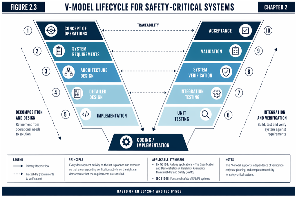 Each design level on the left has a corresponding verification level on the right; the symmetry enforces traceability.
Requirements management is the backbone
The V-model fails when requirements management fails. A typical large US CBTC project starts with stakeholder requirements (5 to 50 in number) that capture business objectives — typical examples include capacity targets in trains per hour, on-time performance commitments, and integration constraints with existing infrastructure. Stakeholder requirements decompose into system-level requirements (500 to 1,500), which decompose into subsystem-level requirements (5,000 to 15,000), which decompose further into component requirements.
Bidirectional traceability links each lower-level requirement to its parent and back again. This is what allows impact analysis when a requirement changes. Modern requirements management tools (IBM DOORS, Jama, Polarion) maintain these linkages; managing 5,000 requirements without tool support is impractical. Requirements quality follows INCOSE principles: each requirement must be verifiable (testable), unambiguous, non-conflicting, traceable, and ranked by criticality.
The traceability work is also the starting point for the safety case. Each safety-related requirement traces to a hazard in the Hazard Log; each hazard traces to a mitigation; each mitigation traces to a verification activity. When the State Safety Oversight reviewer asks how the agency knows that a particular hazard is mitigated, the answer is a traceable chain from requirement to test result. If that chain is broken anywhere, the safety case is incomplete. (For the safety case structure, see The Safety Case Document: What’s Inside, How It’s Reviewed.)
Interface Control Documents and the architecture phase
The V-model’s design phase is where Interface Control Documents (ICDs) get written. ICDs formally define the boundaries between subsystems and between the CBTC system and external systems — the interlocking, the existing power infrastructure, the communication backbone, the rolling stock interface to the Vehicle On-Board Controller. Lack of clear ICDs is a frequent cause of late-stage integration issues on US CBTC projects. The architecture phase is also where safety and reliability budgets are allocated top-down: a stakeholder-level safety target (for example, “the system shall not allow a Signal Passed at Danger more frequently than once per 10⁹ train movements”) decomposes into specific failure rate budgets for the VOBC, the Zone Controller, the Data Communication System, and the interfaces. Each subsystem’s allocation becomes its design target.
The architecture phase ends with two formal milestones: the Preliminary Design Review (PDR), where the system architecture and the high-level design are reviewed, and the Critical Design Review (CDR), where the detailed design is reviewed. Both are gated by the V-model’s traceability requirements: each design decision must be traceable to a requirement, and each requirement must be allocated to a design element.
Verification versus validation
The right arm of the V is split between two distinct activities that procurement documents often conflate:
Verification asks “Did we build it right?” — does the system conform to its specifications? Verification activities include unit testing (with code coverage targets typically at least 80 percent for non-safety code and 100 percent for safety-critical code), subsystem integration testing, and system integration testing in the laboratory environment.
Validation asks “Did we build the right thing?” — does the system meet the stakeholder intent? Validation activities include site integration testing on the actual railway, end-to-end operational testing under representative scenarios, and acceptance testing with the agency in the lead.
A typical V&V plan for a US CBTC project budgets two to four months for laboratory system integration testing and three to six months for on-site integration testing. These figures are routinely underestimated; the cumulative effect of integration surprises (route data inconsistencies, ICD misalignments, unexpected wayside equipment behavior) consistently extends the integration window.
Configuration management, including the site-specific data
Configuration management (CM) maintains system consistency across software CM (source code version control, builds, firmware versions), hardware CM (schematics, PCB layouts, bill of materials), and — critically — site-specific data CM (route data, timing tables, safety parameters). Site-specific data CM is the most often overlooked and a significant source of late-stage CBTC issues. Track design changes after CBTC data has been finalized have caused multi-month delays on multiple US projects. The V-model’s discipline on baselines (Functional Baseline at PDR, Allocated Baseline at CDR, Product Baseline at the end of integration) and on Engineering Change Requests is what prevents this category of issue from accumulating undetected.
Where US projects deviate from the V-model
Several patterns recur in US CBTC projects that have struggled. Each is a deviation from V-model discipline:
Late-started safety work. The Hazard Log and the Hazard Analysis (Preliminary Hazard Analysis at concept stage, System Hazard Analysis at detailed design, FMEA on critical components, Fault Tree Analysis on top events) often begin at 70 to 80 percent design completion. By that point, the architecture is fixed, the interfaces are locked, and any hazard that requires architectural mitigation triggers expensive redesign. The V-model expects the Preliminary Hazard Analysis to start at concept stage and to mature alongside the design.
Incomplete requirements traceability. When a project enters site integration testing and a defect is found, the V-model expects a traceable chain from the failed test back to the requirement that the test was supposed to verify, back to the design decision that was supposed to satisfy the requirement, back to the stakeholder need that drove the requirement. Projects that have not maintained this traceability cannot quickly assess the impact of a defect; they must reconstruct the chain under schedule pressure.
Missing interface owners. When an interface between two subsystems (or between CBTC and an external system like the existing interlocking) does not have a clear owner, miscommunications and late discovery of incompatibility are common. The V-model’s Interface Control Document discipline assigns ownership.
Site-specific data churn. CBTC site-specific data finalization should occur before factory acceptance testing, but agencies sometimes continue to refine track design or operating rules into the integration phase. Each change ripples through the safety case and the test plan.
The Systems Engineering Management Plan
Any FTA-funded CBTC project must deliver a Systems Engineering Management Plan (SEMP) describing organizational roles, the requirements management process and tool, the design review schedule, the V&V strategy, the CM policy, the risk management approach, the integration strategy, and the communication protocols. The SEMP is the agency’s commitment to V-model discipline; it is also the document the FTA will reference if the project deviates from its plan.
Owner’s engineer and Program Management Consultant
US transit agencies typically lack in-house CBTC depth and engage a Program Management Consultant (firms such as WSP, AECOM, HNTB, STV, or Jacobs) to run the systems engineering on the agency’s behalf. The PMC’s V-model role includes requirements development with the agency, vendor oversight on design reviews and architecture validation, interface management and ICD facilitation, acceptance test planning, and safety coordination with the Independent Safety Assessor. The owner’s engineer team is typically three to eight engineers, supported by 20 to 50 vendor engineers. Clear delegation of V-model responsibility between the agency, the PMC, and the vendor is what keeps the project moving; ambiguity at the boundary causes rework and scope creep.
Practical takeaways
- The V-model is the dominant safety-critical systems lifecycle framework. CENELEC EN 50126, EN 50128, and EN 50129 are its rail-specific instantiation; FTA-funded US projects use it as the de facto standard.
- Requirements management with bidirectional traceability is the backbone. Modern projects use DOORS, Jama, or Polarion to manage 5,000 to 15,000 requirements.
- Interface Control Documents must have named owners. Missing or ambiguous interface ownership is a leading cause of late-stage integration issues.
- Verification and validation are distinct. Verification asks whether the system conforms to specifications; validation asks whether the system meets stakeholder intent.
- Configuration management extends to site-specific data, not just software and hardware. Late changes to track data have caused multi-month delays on multiple US projects.
- Hazard analysis must start at concept stage and mature alongside the design. Late-started safety work is the most common cause of safety case rework.
Where to go next
This post is a brief summary. The full treatment lives in Chapter 2 and Chapter 12 of Communications-Based Train Control (Volume 2 on Amazon). Download Chapter 12 slides (free PDF)
Sources
- Wang, C. (2026). Communications-Based Train Control, Volume 2: Deployment, Operations & Strategy. Independent. ISBN 979-8-258-54295-3. — Chapter 12, “Project Lifecycle and Delivery”; Chapter 2, “Standards, Regulations, and the US Framework.”
- CENELEC. EN 50126-1: Railway Applications — Specification and Demonstration of Reliability, Availability, Maintainability and Safety (RAMS).
- CENELEC. EN 50128: Railway Applications — Software for Railway Control and Protection Systems.
- CENELEC. EN 50129: Railway Applications — Safety Related Electronic Systems for Signalling.
- IEEE Standards Association. IEEE Std 1474.1: Standard for Communications-Based Train Control (CBTC) Performance and Functional Requirements.
- INCOSE. Systems Engineering Handbook. International Council on Systems Engineering. incose.org
- Federal Transit Administration. Project and Construction Management Guidelines. transit.dot.gov
Read the full treatment in the book
Chapter 2 of Communications-Based Train Control, Volume 1, covers this in depth.