technical · Article
Wayside Equipment Layout: Antennas, Cabinets, and Cable Routes

A field engineer walking the right-of-way of a Communications-Based Train Control (CBTC) line passes the same set of physical objects every quarter mile: a stainless-steel enclosure on a tunnel wall containing a radio access point and its antenna; a cable tray running along the tunnel ceiling carrying fiber and copper feeds; an equipment room every two to five kilometers housing a Zone Controller pair, a power distribution panel, and an HVAC unit; a balise mounted on the trackbed; an Object Controller cabinet near each switch and signal. The layout is not arbitrary. Each spacing, each elevation, each duct route is the answer to a propagation calculation, a cable-loss budget, a maintenance access requirement, or a civil-works constraint. This article walks the line from the engineer’s perspective and explains what each piece is doing, why it sits where it does, and where the layout decisions actually get made during a CBTC project.
Why layout deserves engineering attention, not just installation attention
Wayside layout looks like an installation problem. It is treated, in too many CBTC projects, as a downstream consequence of architectural decisions made earlier — the supplier specifies the equipment, and a civil contractor figures out where to put it. That treatment is the source of a substantial fraction of CBTC project delays. Equipment-room siting drives fiber-route civil costs; access-point spacing drives commissioning schedule; cable-tray congestion drives change orders. Layout decisions made late in design force expensive rework or compromised performance.
The engineer who can read a wayside layout drawing and challenge the spacing, the routing, and the cabinet count is the engineer who closes a CBTC project on schedule. This article is for that engineer — the systems engineer reviewing a 60 percent design submittal, the construction manager evaluating a contractor’s installation plan, or the operations engineer inheriting the line for the next twenty-five years.
Access points: spacing, elevation, and the propagation budget
The radio access points (APs) are the most visible piece of CBTC wayside infrastructure. They are typically mounted on tunnel walls at the spring line (the height where the tunnel arch transitions from vertical to curved) for tunnel sections, on dedicated steel masts or tunnel-portal supports for elevated structures, and on existing infrastructure poles or purpose-built poles at-grade.
Spacing follows propagation calculations specific to the guideway type. Tunnels are the most demanding: concrete and steel attenuate the signal, multipath dominates, and the antenna pattern is constrained by the tunnel cross-section. Tunnel APs are typically spaced 150 to 350 meters apart, with denser spacing in larger tunnel volumes and at curves where line-of-sight is interrupted. Elevated structures permit 300 to 500 meter spacing because propagation is essentially free-space. At-grade sections sit between, at 250 to 400 meters, with spacing constrained more by foliage, weather, and ambient interference than by attenuation.
The spacing choice is not just about coverage — it is about overlap. Adjacent APs must overlap by 10 to 20 percent of the cell radius so that a moving train always has a connection candidate as it transitions between cells. The fast-roaming budget (covered in End-to-End Latency in CBTC: Where the Milliseconds Go) requires the train to handover within 100 to 150 milliseconds, well below the 250-millisecond comms-loss timeout; without the overlap zone, the handover budget collapses and the system dwells too close to the loss threshold during normal operation.
Antenna elevation matters. An antenna mounted too low is shadowed by passing trains; mounted too high, it loses signal at the platform-floor area where doors and DMI displays need diagnostic data. The standard target is 0.5 to 1.0 meter above the train roof for omnidirectional antennas, oriented along the track for directional antennas. Survey-grade installation matters: a 5-degree pointing error on a directional antenna can move the cell edge by 30 meters, which can put a low-margin platform area into a coverage hole.
Each AP draws 30 to 95 watts via Power-over-Ethernet from the nearest equipment room. A single fiber-and-copper feed from a relay shelter handles both data and power. The single-feed model is cost-efficient but creates a single point of failure; modern designs run dual feeds to each AP or dual fiber-to-Ethernet converters at each location.
Equipment rooms: where the Zone Controller actually lives
Each Zone Controller (ZC) pair lives in a wayside equipment room. The footprint is modest — roughly 20 square meters of floor space for a redundant ZC pair plus power, HVAC, cabling, and access room — but the siting decision drives a substantial fraction of civil-works cost.
Equipment rooms are sited at four kinds of locations. At major stations is the preferred option when station architecture has space; the room can share electrical service, fiber drops, and physical security with station systems, and maintenance access is straightforward. At junctions and crossovers is the right choice when route complexity calls for local interlocking — the ZC and the Electronic Interlocking can co-locate, reducing latency on the route-setting interface (covered in detail in What Is a Zone Controller? CBTC’s Wayside Brain Explained). At maintenance facilities consolidates spare-parts logistics and operational control. In purpose-built wayside enclosures is the option of last resort when none of the above is geographically near where the zone boundary needs to be — typically on long elevated stretches.
The equipment room itself includes the redundant ZC computers in a 19-inch rack, an Uninterruptible Power Supply (UPS) battery sized for two to four hours of run-time, two independent AC feeds with automatic switchover, an HVAC unit maintaining 18 to 25 degrees Celsius and 40 to 60 percent relative humidity, a fire-suppression system (typically gaseous like FM-200 to avoid water damage to electronics), card-access security, and surveillance. HVAC failure is a more common operational problem than electronic failure; the room should be instrumented to alarm to the Operations Control Center (OCC) on temperature or humidity excursion within ten minutes, before the ZC trips on its own thermal protection.
Each ZC equipment room consumes 30 to 50 amperes at 480V AC, plus reserve for its standby. The capital cost of the room itself — civil works, HVAC, UPS, fire suppression, and security — is often comparable to the ZC hardware cost.
The fiber ring: the topology that defines the rest of the layout
The backbone fiber follows a self-healing ring around the line. The standard configuration is a primary ring routed in the duct bank along one side of the right-of-way, plus a secondary path either as a second physical route or as a Parallel Redundancy Protocol (PRP) instance over the same fiber pair using independent transceivers. (For why ring topology with PRP/HSR matters for safety availability, see End-to-End Latency in CBTC: Where the Milliseconds Go.)
The ring enters the equipment room at each ZC site, drops a connection to the ZC’s network switch, and continues to the next site. Total installed fiber for a 30-kilometer line typically runs 60 to 80 kilometers when accounting for slack, riser drops, and future-growth conduit. Installed cost varies enormously with civil conditions but tends to fall in the range of $50,000 to $120,000 per route-mile in US deployments, with tunnel sections at the high end and surface right-of-way at the low end.
The ring is sized for safety availability, not for bandwidth. A Zone Controller managing 30 trains generates 5 to 20 megabits per second of safety traffic; modern rings carry 1 to 10 gigabits per second. Most of the bandwidth is consumed by surveillance video, passenger Wi-Fi backhaul, and station systems. The CBTC-vital traffic occupies its own VLAN with QoS prioritization (covered in The Cybersecurity Surface of a Modern CBTC System) so that congestion on the non-vital VLANs cannot starve safety messages of bandwidth.
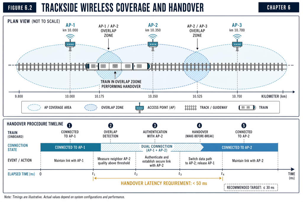 Every wayside element traces back to a propagation budget, a cable-loss calculation, or a maintenance-access requirement. Spacing is not arbitrary.
Cable trays: the unglamorous integration problem
Cable trays carry the fiber, the AP power-and-data drops, the interlocking field cabling, the SCADA control circuits, and the legacy signaling cables that the CBTC overlay does not displace. Tray congestion is the dominant integration problem in tunnel CBTC retrofits. The tunnel was originally built with cable capacity sized for the original signaling system; CBTC adds two to three times the cable mass, often with separation requirements (vital signaling cabling separated from non-vital, fiber separated from copper, signal cabling separated from traction power feeders).
The standard layout in a US transit tunnel runs cable trays at one or two elevations on each tunnel wall. The upper tray typically carries communications (fiber, copper data), the lower tray carries power and traction cables, and signaling cabling sits in a separate ladder rack with explicit separation. Crossings — where a cable must cross from one wall to the other — are the highest-failure-rate locations because they are where physical damage from foreign objects, wheel debris, and water intrusion concentrates.
A 60 percent design review should explicitly check cable-tray fill ratios. Trays filled above 40 percent capacity at design time will be over capacity by Year 5 once spare cables, change-order additions, and operations-and-maintenance cables accumulate. The marginal cost of a larger tray at construction is small; the cost of replacing an undersized tray five years later, in service, is substantial.
Object Controllers: the field interface to switches and signals
At each switch and at each remaining wayside signal, an Object Controller (OC) cabinet provides the field interface between the ZC and the physical equipment. The OC is typically housed in a small trackside cabinet — 1.0 to 1.5 meters tall, weather-sealed, with its own UPS and heater — adjacent to the switch machine or signal mast.
The OC cabinet is small but its location is constrained. It must be close enough to the field equipment that low-voltage control circuits remain robust (typically within 50 meters of the switch machine) and accessible enough that a technician can reach it from the right-of-way without entering live track. In retrofit projects, the OC cabinet location often forces civil work — relocating an existing electrical cabinet, demolishing a relay shelter that has been on the line since the 1960s, or building a new concrete pad with grounding and conduit to the field equipment. These civil items are easy to underestimate and routinely become schedule-critical.
Maintenance access: the requirement that wins on day-1 of operations
Every wayside element has a maintenance access requirement that is enforced by FRA, FTA, and OSHA workplace-safety rules: a technician must be able to reach the equipment safely, with the line either out of service or under appropriate flagging, within a reasonable time bound. An AP mounted high on a tunnel wall requires an articulated lift that the tunnel ceiling height permits. An equipment room behind a station platform requires a back-of-house corridor wide enough for spare-parts handling. A balise embedded in the trackbed requires a track-possession window for inspection.
Maintenance access is easy to omit at design time and impossible to retrofit cheaply. The construction-document review should explicitly verify access procedures for each class of wayside equipment: who reaches the AP, in what time window, with what equipment, and what does the line need to do during the access. A layout that looks elegant on the drawing but requires a four-hour line shutdown to swap an AP is operationally unacceptable.
Practical takeaways
- Wayside layout is engineering, not installation. The spacing, elevation, and routing decisions made in design fix the field-engineering cost, the commissioning schedule, and the operational maintenance burden for the next twenty-five years.
- AP spacing follows propagation: 150 to 350 meters in tunnels, 300 to 500 meters on elevated structures, 250 to 400 meters at-grade, with 10 to 20 percent overlap between adjacent cells. Antenna elevation, pointing, and feeder redundancy each have a specification answer that should appear in the design review.
- Equipment rooms drive civil-works cost more than they drive equipment cost. Siting at stations, junctions, or maintenance facilities — rather than purpose-built wayside enclosures — is preferred when the geography permits.
- The fiber ring is sized for safety availability, not for bandwidth. The CBTC-vital traffic gets its own VLAN with QoS prioritization on a converged backbone.
- Cable-tray fill is the most common integration problem in tunnel retrofits. Design at 30 to 35 percent fill to leave capacity for growth; design at 40 percent or above and pay for it later.
- Maintenance access requirements should be verified per equipment class at construction-document review. A clever layout that requires a four-hour line shutdown for an AP swap is operationally unacceptable.
Where to go next
This post is a 10-minute summary. The full treatment of wayside equipment, equipment-room infrastructure, and communication-network layout lives in Chapter 5 and Chapter 6 of Communications-Based Train Control (Volume 1 on Amazon). Download Chapter 5 slides (free PDF) and Chapter 6 slides.
For how the Zone Controller in the equipment room generates Movement Authorities, see What Is a Zone Controller? CBTC’s Wayside Brain Explained. For why storage yards present a different layout problem, see CBTC in Storage Yards: Why It’s a Different Engineering Problem.
Sources
- Wang, C. (2026). Communications-Based Train Control, Volume 1: Foundations & Technical Architecture. Independent. ISBN 979-8-258-54295-3. — Chapter 5, “Wayside Equipment”; Chapter 6, “Communication Systems.”
- IEEE Standards Association. IEEE Std 1474.1: Communications-Based Train Control (CBTC) Performance and Functional Requirements.
- International Electrotechnical Commission. IEC 61373: Railway applications — Rolling stock equipment — Shock and vibration tests.
- IEEE Standards Association. IEEE Std 802.11: Wireless LAN Medium Access Control (MAC) and Physical Layer (PHY) Specifications.
- Federal Communications Commission. Part 90: Private Land Mobile Radio Services. fcc.gov/wireless/bureau-divisions/mobility-division/private-land-mobile
- Federal Transit Administration. State Safety Oversight Program. transit.dot.gov/regulations-and-guidance/safety/state-safety-oversight
- MTA New York City Transit. Communications-Based Train Control Status Update. new.mta.info/project/communications-based-train-control-cbtc
- BART. Train Control Modernization Program. bart.gov/about/projects/tcmp
How this article was produced. Drafted with AI assistance, then reviewed and fact-checked by Chunjun (Francisco) Wang against Communications-Based Train Control (the author's two-volume reference) and primary sources — agency records, vendor documentation, and IEEE/IEC standards. Every date, vendor, and figure is traceable to a cited source. Spot a mistake? Corrections are welcome via the contact page.
Read the full treatment in the book
Chapter 5 of Communications-Based Train Control, Volume 1, covers this in depth.