definitional · Article
What Is a Zone Controller? CBTC's Wayside Brain Explained
The MTA’s Communications-Based Train Control deployment on the 8.6-kilometer L Line is divided into three contiguous Zone Controller territories, each housed in a wayside equipment room and each operating in a hot-standby configuration with a paired backup. Every train inside any one of those territories is, at every instant, owned by exactly one Zone Controller, which knows the train’s position, generates its Movement Authority every cycle, and coordinates handover to the next Zone Controller before the train crosses a territory boundary. The Zone Controller is the wayside brain of CBTC. It is also the most expensive and most architecturally consequential piece of wayside equipment a transit agency procures. This post explains what a Zone Controller actually does, how it is sized, why redundancy is non-negotiable, and what an agency should specify in an RFP that names one.
Why this matters
The Zone Controller is the SIL 4 wayside computer that owns a defined geographic territory of the railway. It is the layer that turns moving-block from a concept into a production system. For a procurement engineer, the Zone Controller is the wayside equivalent of the onboard Vehicle On-Board Controller: it is where the safety-critical logic lives, where redundancy must be uncompromising, and where vendor lock-in tends to crystallize. The Zone Controller is also the component most often misunderstood in non-technical conversations about CBTC, where the architecture is sometimes presented as a single centralized computer. It is not. The architecture is deliberately distributed, and understanding why is part of understanding why CBTC scales.
Territory: how big is a zone
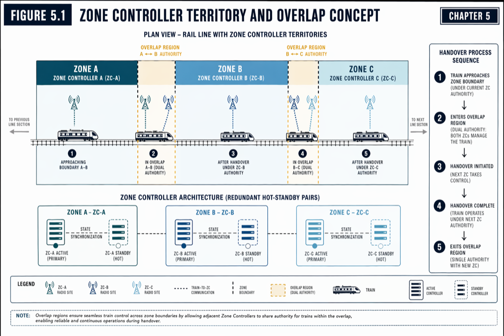
A Zone Controller owns a contiguous segment of track, typically 2 to 5 kilometers in length. Territory size is a deliberate engineering decision, balancing four factors.
Smaller territories localize faults: if a Zone Controller fails, only the trains in its territory are affected, while adjacent territories continue normally. Smaller territories also reduce the load on each Zone Controller; a busy metro line carrying ten trains in a 3-kilometer territory imposes far less computational burden than the same ten trains in a 15-kilometer territory.
Larger territories reduce capital cost: each Zone Controller requires its own equipment room, redundant power, environmental controls, network connections, and a hot-standby pair. Halving the territory size doubles the wayside equipment count.
Latency considerations push toward smaller territories: a Zone Controller close to its trains has shorter radio paths, lower communication latency, and tighter MA cycle times.
The empirical answer for US heavy-rail metro deployments converges on roughly 2 to 5 kilometers per zone, with denser zoning at junctions and station clusters where computational and communication burden is highest. A typical 20-kilometer line carries five to seven Zone Controllers; a 50-kilometer line carries 12 to 15.
Hot-standby: why redundancy is not optional
Every production Zone Controller is deployed as a hot-standby pair. Two physically distinct units, both operating, both receiving the same inputs, both running identical computation, but only one actively issuing Movement Authorities. The standby tracks the primary’s state through a continuous heartbeat (typically every 100 milliseconds) and assumes control automatically if the primary fails or stops responding.
The required failover time is well under one second, typically 500 milliseconds. The architectural reason is operational: a moving train cannot afford a multi-second gap in authority generation. If the primary Zone Controller fails and the standby takes 5 seconds to assume control, every train in the territory hits its MA validity window and applies brakes; service collapses across the territory. With sub-second failover, trains do not perceive the takeover.
The two units in a hot-standby pair are typically co-located in the same equipment room (for cost and operational simplicity) but on independent power feeds, independent network paths, and independent computing hardware. Some high-availability deployments separate them geographically, with the primary in one equipment room and the standby in a different room kilometers away, connected by redundant fiber. The geographic separation defends against equipment-room-scale failures (fire, water, HVAC failure) at the cost of more complex synchronization.
A Zone Controller pair is, in turn, redundant inside each unit. The most common configuration is 2-out-of-2 voting: two independent processors run identical safety logic, and a hardware comparator validates that they produce matching results every cycle. Disagreement triggers a safe-state transition, typically a service brake command to all trains followed by failover to the standby unit. Some high-integrity deployments use 2-out-of-3 voting, where three processors vote and the majority result wins. The choice trades cost against fault tolerance.
 A Zone Controller pair: primary issues authorities, standby tracks state via heartbeat, and failover completes in under 500 ms.
What a Zone Controller actually does
The Zone Controller’s job has six discrete responsibilities, each of which must work correctly every cycle.
It receives position uplinks from every train in its territory, every 500 milliseconds to 1 second per train. Each uplink carries train identifier, position (route and offset), speed, direction, declared braking performance, and operational status. The Zone Controller validates the message authentication, sequence numbers, and freshness, and rejects any uplink that fails the checks.
It maintains a track occupancy model — a real-time database of every train in its territory, with position, speed, and uncertainty bound. The model is updated every cycle from incoming uplinks; trains that fail to report within a configurable timeout are flagged as potentially missing and trigger conservative authority generation.
It computes Movement Authorities for every train. The computation considers the position of trains ahead (with safety margin), the next switch or junction whose route is not yet locked, the next civil or temporary speed restriction, and the boundary of the Zone Controller’s territory. The minimum of these candidate distances becomes the end-of-authority point, and the deceleration curve from current speed to a stop at that point becomes the speed profile. The MA is signed and transmitted back to the train. (For the MA mechanics, see The Movement Authority Concept: How a CBTC Train Decides How Far to Go.)
It coordinates with the electronic interlocking. Before granting authority through a switch, the Zone Controller requests a route from the interlocking, waits for confirmation that the route is set and locked, and only then extends the train’s MA past the switch. If the interlocking cannot set the requested route — because of a conflicting route, a switch failure, or a track occupancy detection — the Zone Controller denies the authority extension and the train holds short of the junction.
It manages zone-boundary handover. As a train approaches the territory boundary, the current Zone Controller initiates a handover sequence with the adjacent Zone Controller, transmitting train state and projected position. The adjacent Zone Controller acknowledges, confirms it can accommodate the inbound train, and prepares to issue authorities once the boundary is crossed. Handover is choreographed: a few hundred milliseconds of overlap during the boundary crossing ensures continuous authority with no gap.
It reports to the central Automatic Train Supervision (ATS) system. The Zone Controller transmits zone-level summaries to ATS every 1 to 2 seconds: train positions, MA boundaries, equipment status, alarms, and operational events. ATS uses this for line-level dispatching, schedule regulation, dispatcher displays, and incident logging.
What is in the equipment room
A Zone Controller is not a single rack-mount computer; it is an equipment room. A typical wayside equipment room for one Zone Controller pair contains:
- Two server-grade industrial computer chassis (primary and standby Zone Controller), each with redundant 2-out-of-2 or 2-out-of-3 internal processor configuration, ECC memory, and redundant power supplies.
- Network equipment: redundant managed Ethernet switches connecting the Zone Controller pair to the central ATS over a dedicated fiber backbone, to local Wayside Access Points over Ethernet, and to the electronic interlocking over either Ethernet or legacy serial protocols.
- Uninterruptible Power Supply: typically 48V DC battery-backed UPS rated for 2 to 4 hours of full-load operation, allowing controlled degraded operation during a mains failure.
- HVAC and environmental controls: split-unit air conditioning maintaining 18 to 25 degrees Celsius year-round, humidity control, and smoke and water detection.
- Fire suppression: typically gaseous suppression (FM-200 or Novec, increasingly preferred over wet-pipe sprinklers in equipment rooms) or, in older facilities, a wet-pipe sprinkler system with gasketed equipment racks.
- Physical security: locked enclosure, card-access door, intrusion detection, and CCTV. The Zone Controller is SIL 4 safety-critical equipment; unauthorized access is a credible threat to the safety case.
The construction cost of a new wayside equipment room is meaningful: industry references put it at roughly $200,000 to $400,000 depending on civil and HVAC complexity. Retrofitting an existing utility building or signal house can be cheaper. On a 20-kilometer line with five Zone Controller territories, that is $1 to $2 million in equipment-room civil cost alone before the Zone Controller hardware itself.
What an RFP should specify
The most common procurement mistake on the Zone Controller side is underspecification. Vendors will deliver to whatever the RFP names; what the RFP omits, the vendor will optimize away. The minimum specification list:
Territory sizing methodology. Specify maximum territory length, expected train count per territory at peak, and how the vendor should adjust if line densification changes the design point. Vendors that quote a fixed equipment count without explaining the underlying sizing methodology are quoting against the wrong problem.
Failover requirements. Specify hot-standby with bounded failover time (typically <500 ms), required redundancy mode (2oo2 versus 2oo3), and acceptable degraded operation during failover.
MA cycle time. Specify the minimum cycle time required to support the headway target. A 90-second peak headway typically requires a 500-ms cycle; a 70-second peak headway pushes toward 250 ms.
Interlocking interface. Specify the interface protocol, the latency budget for route requests, and the failure modes for interlocking unavailability. Many CBTC delays come from underspecified interlocking integration. (For the broader interface picture, see Chapter 5 of the manuscript.)
Zone boundary handover. Specify the handover protocol, the maximum allowable speed restriction at boundaries during handover, and the failure mode for handover failure. Best-in-class deployments achieve seamless handover with no speed restriction; the L Line is a public reference point.
Equipment-room infrastructure. Specify whether the vendor or the agency provides the equipment room, the environmental and security requirements, and the responsibility for power, HVAC, and physical access.
Practical takeaways
- A Zone Controller owns a 2- to 5-kilometer territory and generates Movement Authorities for every train in it every cycle.
- Hot-standby redundancy is not optional. Specify <500 ms failover time and either 2oo2 or 2oo3 internal voting.
- Equipment-room civil and HVAC cost is real (commonly $200,000 to $400,000 per room) and easy to underbudget.
- Interlocking integration and zone-boundary handover are the two interfaces most commonly underspecified in RFPs and most commonly responsible for project delay.
- The Zone Controller is the wayside equivalent of the onboard VOBC. Both are SIL 4. Both are safety-critical. Both deserve the same procurement rigor.
Where to go next
This post is a brief overview. The full treatment lives in [Chapter 5 — Wayside Equipment] of Communications-Based Train Control (Volume 1 on Amazon). Download Chapter 5 slides (free PDF →)
Sources
- Wang, C. (2026). Communications-Based Train Control, Volume 1: Foundations & Technical Architecture. Independent. ISBN 979-8-258-54295-3. — Chapter 3, “CBTC System Architecture Overview”; Chapter 5, “Wayside Equipment.”
- IEEE Standards Association. IEEE Std 1474.1: Standard for Communications-Based Train Control (CBTC) Performance and Functional Requirements.
- International Electrotechnical Commission. IEC 62290-1: Railway applications — Urban guided transport management and command/control systems.
- International Electrotechnical Commission. IEC 61508: Functional Safety of Electrical/Electronic/Programmable Electronic Safety-related Systems.
- CENELEC. EN 50129: Railway applications — Safety related electronic systems for signalling.
- MTA New York City Transit. L Line CBTC Project Overview. new.mta.info
- BART. Train Control Modernization Program. bart.gov/about/projects/tcmp
How this article was produced. Drafted with AI assistance, then reviewed and fact-checked by Chunjun (Francisco) Wang against Communications-Based Train Control (the author's two-volume reference) and primary sources — agency records, vendor documentation, and IEEE/IEC standards. Every date, vendor, and figure is traceable to a cited source. Spot a mistake? Corrections are welcome via the contact page.
Read the full treatment in the book
Chapter 3 of Communications-Based Train Control, Volume 1, covers this in depth.