CBTC Architecture Diagram
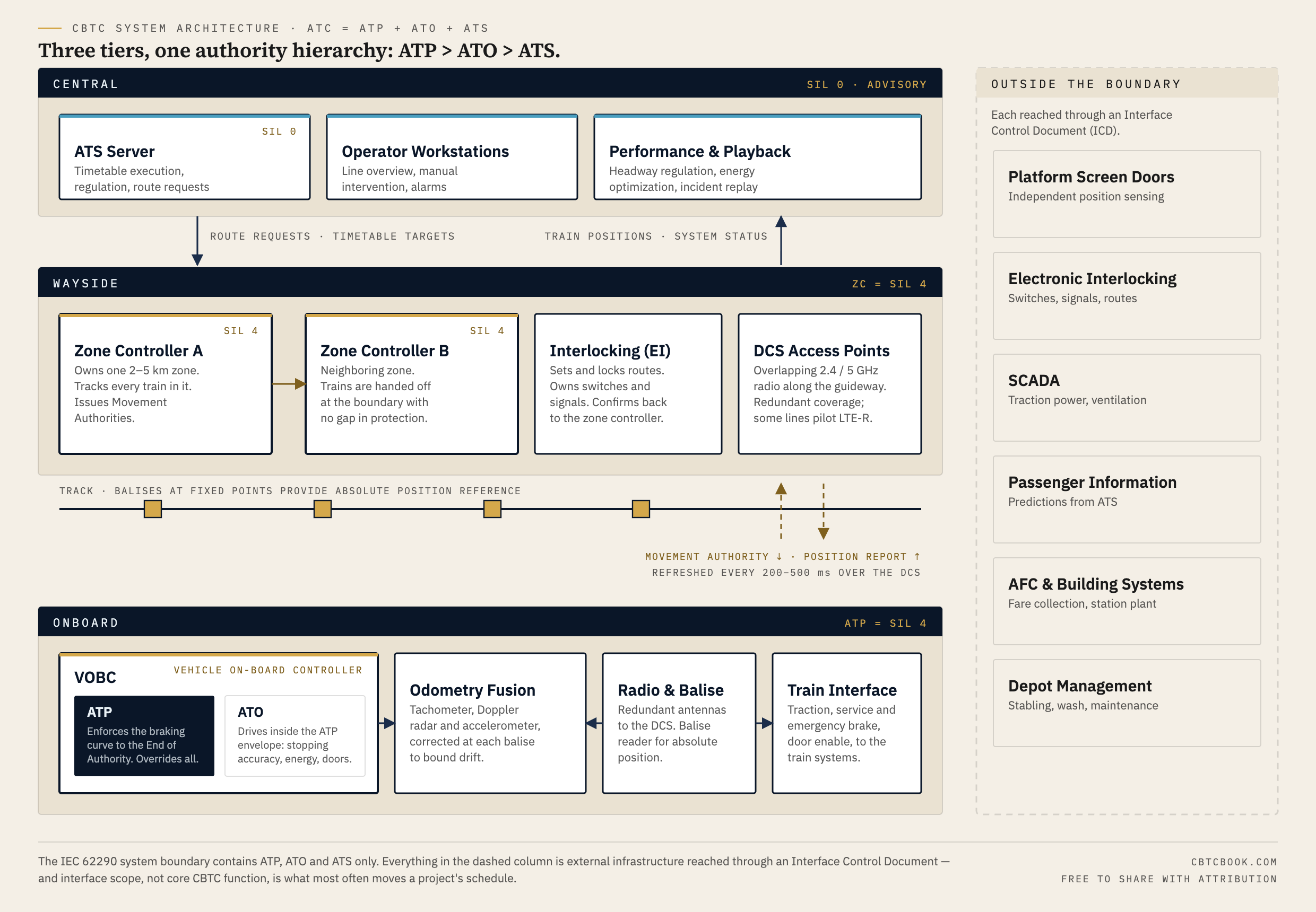
Most CBTC block diagrams in circulation are either a vendor's marketing cut or a redrawn textbook figure with the interfaces left out. This one draws the boundary explicitly: what is inside the IEC 62290 system, what is outside it, and what has to be written into an Interface Control Document before anyone signs.

Free to use and share with attribution. No email required.
What's inside
- All three physical tiers — central ATS, wayside zone controllers and interlocking, onboard VOBC — with the real subsystem breakdown inside each.
- The ATP / ATO nesting drawn as it actually is: ATO drives inside the envelope ATP defines, never outside it.
- Movement Authority and position reporting labeled with real timing (refreshed every 200–500 ms over the DCS).
- Zone-controller handoff at the zone boundary, and balise placement for absolute position reference.
- The six external systems that sit outside the boundary behind an ICD — the usual source of schedule slip.
- Vector SVG, so you can recolor it or pull pieces into your own slides.
The boundary is the point
Per IEC 62290, the CBTC system comprises ATP, ATO and ATS — and nothing else. Platform screen doors, the interlocking, SCADA, passenger information, fare collection and the depot are all external infrastructure reached through defined interfaces. That distinction looks academic on a diagram and is anything but in a project: interface scope, not core CBTC function, is the leading cause of the delays that make the trade press.
The dashed column on the right of this sheet exists to make that visible in a design review. If a bidder's architecture drawing does not separate those systems, or the RFP has no Interface Control Document naming message formats, latency budgets, failure modes and acceptance criteria for each one, the risk has not been priced — it has been deferred.
Authority runs one way
ATP > ATO > ATS, without exception. ATS is advisory and non-safety-critical (SIL 0): it proposes timetable targets and route requests. ATO optimizes against those targets but only inside the speed-versus-distance envelope ATP maintains. When they conflict, ATP applies the brake and wins. Every box and arrow on this diagram is arranged to make that hierarchy readable at a glance.
Sources & method
Drawn for Communications-Based Train Control, Volume 1, Chapter 3, by Chunjun (Francisco) Wang. Subsystem decomposition and the system boundary follow IEC 62290; Movement Authority refresh rates and zone lengths reflect current deployment practice as documented in the manuscript.