technical · Article
ATS Dispatcher Workstation: What It Looks Like in 2026

A visitor walking into the Operations Control Center (OCC) of a modern US transit agency sees an unmistakable physical pattern: a long arc of dispatcher workstations, each with five or six monitors arranged in a curved bezel; a wall-mounted large-screen overview display ten to twenty feet wide showing the entire network at a glance; an open layout with sight lines from each dispatcher to the chief controller’s position and to the wall display; lighting tuned to ISO 11064 with glare-free desk surfaces; an ambient noise level deliberately kept low so that radio communication and verbal coordination remain intelligible. The workstation is the seat where the Automatic Train Supervision (ATS) layer of Communications-Based Train Control (CBTC) actually meets the dispatcher who runs service. This article walks through the physical anatomy of a 2026-vintage workstation, the HMI conventions that have converged across vendors, and the design decisions that determine whether a dispatcher can hold attention through a 12-hour shift on a busy line.
Why the workstation is part of the system, not an afterthought
The dispatcher workstation is often the last piece specified in a CBTC procurement and the first piece the agency interacts with every day. Vendors typically deliver the workstation as a “human-machine interface” package that includes screens, software, and ergonomic furniture. Agencies typically accept it without the depth of engineering review they apply to the Zone Controllers.
That treatment is mistaken. The workstation determines decision speed, error rates, and operator fatigue. It is the place where ATS information becomes operational action; it is the place where service-affecting incidents are diagnosed and resolved; it is the place where regulatory inspections evaluate operational competency. A workstation designed without rigorous human-factors discipline produces dispatcher errors and slow incident response that no amount of upstream signaling sophistication can compensate for.
This article is for the systems engineer or operations director who needs to evaluate a vendor’s workstation offering, write a workstation specification for a procurement, or critique an existing OCC layout against current human-factors practice.
The monitor configuration: three to six screens
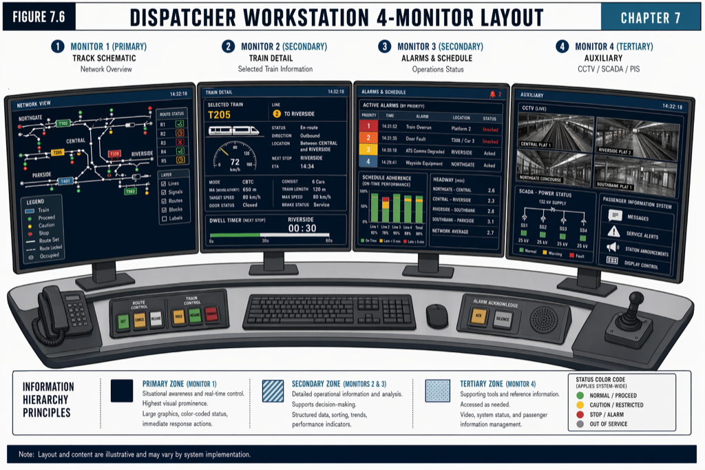
A dispatcher workstation in 2026 typically carries five monitors. Smaller agencies on simpler lines may use three; larger agencies on busy multi-line corridors may use six. The configuration converges on a function-per-monitor partition.
The primary display is centered in front of the dispatcher, typically a 27- to 32-inch display at the operator’s eye level. It carries the real-time line map: train symbols, speed readouts, signal aspects (where wayside signals exist), next-station predictions, and the alarm strip. The dispatcher’s attention defaults here during normal operation.
The alarm and event log sits to one side, dedicated to time-stamped event listing with severity color coding. Alarms appear here first; the dispatcher acknowledges or escalates from this display.
The schedule and timetable display shows the timetable view: planned versus actual arrival times at each station, late or early indicators per train, predicted recovery time from any current delay. This display is where schedule regulation decisions are made.
The train detail display is the drill-down view for an individual train: its position with sub-meter precision, speed, fault status, current operating mode, ATO state, door state, communication link health. Dispatchers select a train on the primary display and the train detail display populates.
The video and CCTV display is dedicated to platform cameras, train-interior cameras, and emergency-event automatic-cued video. On systems where ATS triggers automatic camera selection on emergency events, this display becomes the dispatcher’s primary tool for situational assessment in the seconds after an alarm.
A sixth display, where present, typically carries SCADA traction-power status, environmental conditions (weather, station HVAC, escalator outages), and inter-OCC coordination tools. It is monitored peripherally rather than continuously.
The monitor arrangement is not a stack of equal-priority panels. The eye-tracking literature in control-center design consistently finds that operators concentrate attention on the central two displays for 80 percent of working time and reference the others on demand. The HMI must support this attentional pattern: critical information goes to the central displays; reference information goes to the peripheral displays; alarms must propagate visually across the array so the dispatcher catches them regardless of where they are looking.
ISO 11064: the standard that governs the room around the workstation
Workstations do not stand alone. They sit inside a control center designed to ISO 11064 — the international standard for ergonomic design of control centers. ISO 11064 specifies the physical dimensions of the workstation (desk height, knee clearance, monitor distance), the lighting (200 to 300 lux average, with glare control on desk and monitor surfaces), the acoustic environment (ambient noise below 50 dBA so that voice communication remains intelligible), the temperature (20 to 24 degrees Celsius, controlled ±2 degrees to prevent fatigue), and the layout of the control room as a whole (sight lines, traffic flow, emergency egress, separation between operational and visitor areas).
The standard is not aspirational; it is the operating reference for any modern OCC. Agencies that procure dispatcher workstations without specifying ISO 11064 compliance routinely receive workstations that fail human-factors review in operations.
 ISO 11064 governs the room. Workstation specification without OCC layout specification produces predictable human-factors failures.
HMI color conventions and the alarm hierarchy
Two HMI conventions have converged across major US transit ATS deployments: the color coding for train and infrastructure state, and the alarm hierarchy.
Color coding. Green indicates normal operation. Yellow indicates degraded operation, schedule deviation, or a non-critical alarm requiring attention. Red indicates an active critical alarm or unsafe condition. Blue indicates manual or restricted-mode operation. Gray indicates equipment out of service. Black or dark backgrounds reduce eye fatigue during long shifts; white backgrounds are used for status panels where readability under varied lighting matters more than long-shift comfort. The conventions are not legal requirements but they are operational expectations; a vendor that delivers an HMI with non-standard color coding produces a learning curve the agency rarely accepts.
Alarm hierarchy. Modern ATS alarm management organizes alarms into severity tiers (typically Critical, High, Medium, Low) with explicit acknowledgement and escalation paths. The HMI displays alarms in priority order, suppresses dependent alarms (a “communication loss to Zone 5” alarm suppresses the cascade of “Zone 5 train” alarms that follow), and applies rate-limiting to prevent the operator from being flooded by repetitive low-severity events. ISA 18.2, EEMUA 191, and the underlying human-factors literature on alarm management are the canonical references; the HMI software should implement these patterns out of the box.
The alarm strip on the primary display is the single most important HMI element after the line map. It must be large enough to read at peripheral vision, must distinguish severities visually without color-coding alone (color-blind accessibility requires shape and pattern as well), and must persist alarms until explicitly acknowledged. An alarm strip that scrolls alarms off the screen before the dispatcher has acknowledged them is an HMI defect.
The Large-Screen Overview Display
The wall-mounted Large-Screen Overview Display (LSD) is the shared situational-awareness surface in the OCC. It is typically 10 to 20 feet wide, mounted at the front of the workstation arc, visible to every dispatcher and to the chief controller. Modern installations use LED video walls or projection systems with brightness adequate for the room lighting and resolution adequate for the entire network to be displayed at usable detail.
The LSD shows the line map (or network map for multi-line operations), train positions and identities, station occupancy, alarms in summary form, and key performance indicators (current headway, on-time performance, system availability). Critically, it shows the system view, not the individual dispatcher’s working view. The LSD is where the chief controller, supervisors, and visiting executives see what the dispatchers are managing. It is also where collaborative incident response coordinates: when a major incident develops, multiple dispatchers and the chief controller orient on the LSD as the shared frame of reference.
A common procurement mistake is to under-size the LSD. A 10-foot LSD on a 30-mile network forces the dispatcher to choose between zoom level (resolution per train) and span (entire network visible). On a busy multi-line network, an LSD smaller than 16 feet with 4K resolution is usually inadequate for the operational role.
Role-based workstation customization
Not all dispatchers do the same job. Modern ATS deployments support role-based workstation profiles that present different HMI configurations for different roles.
A primary line dispatcher has the full HMI: line map, schedule, train detail, alarms, video, SCADA. The primary dispatcher has full command authority over routes, dwell, and emergency responses on their assigned line.
A secondary support or power controller has a simplified HMI focused on the support function: SCADA-heavy for the power controller, alarm-and-incident-coordination for the secondary support. The HMI should not present command capabilities the role does not exercise; cluttering the HMI with unused commands is a source of errors.
A station manager or platform supervisor has a remote-workstation subset: door control for the assigned station, local PA, platform camera feeds, alarm acknowledgment. This role is increasingly common as agencies push station-level monitoring out of the central OCC.
A chief controller has a consolidated overview of multiple line dispatchers’ positions, with escalation authority for cross-line incidents. The chief controller’s workstation typically does not carry the line-map detail of an individual dispatcher; it carries cross-line summaries and inter-line coordination tools.
Role-based customization reduces cognitive load and reduces the risk of inadvertent command entry from a role that does not normally exercise that command.
Operational continuity: the redundant OCC
A single OCC is a single point of failure. Modern US transit agencies pair the primary OCC with a backup OCC, typically at a geographically separate site. The backup site is staffed during major incidents or when the primary site is unavailable; it carries identical workstation configurations and identical HMI software so that dispatchers can work either site without retraining. State synchronization between the two sites is real-time, with the backup site able to assume primary control within minutes of a primary-site failure.
The cybersecurity envelope around the OCC is substantial; the workstations are inside the highest-security zone of the operational technology network, with no email, no general internet, and no removable media (covered in The Cybersecurity Surface of a Modern CBTC System). Multi-factor authentication for dispatcher login is standard. Session recording for compliance and post-incident review is increasingly common.
What an agency should specify
A workstation procurement that wants to control quality should require the supplier to deliver against six specific items.
ISO 11064 compliance certificate or equivalent independent ergonomic review of the workstation furniture, monitor configuration, and physical environment.
HMI color coding and alarm hierarchy specification matching agency conventions, with explicit accessibility provisions for color-blind operators.
Role-based workstation profiles for at least line dispatcher, secondary support, power controller, station supervisor, and chief controller, with documented authorization paths for switching between profiles.
LSD sizing analysis showing that the chosen size and resolution support the operational view (network span at usable detail) without forcing a zoom-versus-span tradeoff.
Redundant OCC interoperability demonstrating that primary and backup sites carry identical configurations and that state synchronization meets the agreed RPO and RTO.
Cybersecurity hardening of the workstation operating system, with explicit account management, MFA, session logging, and removable-media policy.
Practical takeaways
- The dispatcher workstation is where ATS becomes operational action. It deserves the same engineering rigor as the Zone Controller, not a procurement afterthought.
- Modern workstations carry five monitors with a function-per-monitor partition: primary line map, alarm and event log, schedule and timetable, train detail, video and CCTV. A sixth monitor for SCADA and reference is increasingly standard.
- ISO 11064 governs the room around the workstation. Specifying it is the single most cost-effective discipline for ensuring the OCC is fit for purpose.
- HMI conventions have converged on a green-yellow-red-blue-gray color hierarchy and an ISA 18.2-style alarm hierarchy with priority sorting, dependent suppression, and rate limiting. Agencies should expect both as out-of-the-box behavior.
- The Large-Screen Overview Display is the shared situational-awareness surface. Under-sizing it forces the dispatcher into an unfair zoom-versus-span tradeoff and degrades collaborative incident response.
- Role-based workstation profiles reduce cognitive load and reduce the rate of inadvertent command entry. They should be specified in procurement, not configured ad hoc post-deployment.
- A workstation procurement that specifies ISO 11064 compliance, HMI standards, role-based profiles, LSD sizing, redundant-site interoperability, and cybersecurity hardening produces a substantively better OCC than one that does not.
Where to go next
This post is a 10-minute summary. The full treatment of the Automatic Train Supervision layer, the OCC, dispatcher workstation design, and large-screen displays lives in Chapter 7 of Communications-Based Train Control (Volume 1 on Amazon). Download Chapter 7 slides (free PDF).
For the broader functional context, see ATP, ATO, ATS: The Three-Layer Triad of Modern Train Control. For the cybersecurity envelope around the OCC, see The Cybersecurity Surface of a Modern CBTC System. For why the dispatcher’s dwell-time discipline is the largest short-term lever on operational performance, see Door Control in CBTC: The Unglamorous System That Causes the Most Failures.
Sources
- Wang, C. (2026). Communications-Based Train Control, Volume 1: Foundations & Technical Architecture. Independent. ISBN 979-8-258-54295-3. — Chapter 7, “Central System and ATS.”
- International Organization for Standardization. ISO 11064: Ergonomic design of control centres.
- International Society of Automation. ANSI/ISA 18.2: Management of Alarm Systems for the Process Industries.
- Engineering Equipment and Materials Users Association. EEMUA Publication 191: Alarm Systems — A Guide to Design, Management and Procurement.
- IEEE Standards Association. IEEE Std 1474.1: Communications-Based Train Control (CBTC) Performance and Functional Requirements.
- Federal Transit Administration. State Safety Oversight Program. transit.dot.gov/regulations-and-guidance/safety/state-safety-oversight
- MTA New York City Transit. Rail Control Center Modernization. new.mta.info
- BART. Train Control Modernization Program. bart.gov/about/projects/tcmp
How this article was produced. Drafted with AI assistance, then reviewed and fact-checked by Chunjun (Francisco) Wang against Communications-Based Train Control (the author's two-volume reference) and primary sources — agency records, vendor documentation, and IEEE/IEC standards. Every date, vendor, and figure is traceable to a cited source. Spot a mistake? Corrections are welcome via the contact page.
Read the full treatment in the book
Chapter 7 of Communications-Based Train Control, Volume 1, covers this in depth.