definitional · Article
How CBTC Trains Know Where They Are (Without Track Circuits)
The Brooklyn-bound L Line train pulling out of Eighth Avenue at 8:42 in the morning has no GPS lock. It is in a hundred-year-old steel-jacketed tunnel with the East River above it; satellites are not an option. But the wayside Zone Controller, in real time, knows where the train is to within roughly one to two meters. It updates that position every cycle and uses it to compute a Movement Authority that ends a precise braking distance behind the rear of the train ahead. How the train obtains that position fix, when it cannot see the sky, is one of the most elegant pieces of engineering in modern transit. It is also one of the most commonly underestimated. This post explains the sensor fusion that makes high-resolution train localization work, why each sensor exists, and how the architecture handles the inevitable failures.
Why localization is the entire game
Without high-resolution train position, moving block does not work. The whole capacity advantage of CBTC over fixed-block signaling rests on the wayside knowing exactly where each train is, not just inferring “somewhere within a 300-meter block.” If localization accuracy degrades from one meter to ten meters, the safe-following margin grows by nine meters per train, and the headway gain that justifies the project disappears. (For the underlying capacity math, see Moving Block Explained: Why It Replaced Fixed Block.) Every CBTC RFP that an agency writes should specify localization accuracy explicitly: typical performance numbers are one to two meters under normal conditions, two to five meters under degraded conditions, with bounded uncertainty growth between balise reads.
This post is for the systems engineer or program manager who needs to understand what those accuracy numbers actually depend on, and what a vendor is signing up to deliver.
Why GPS is not the answer
The intuitive question, particularly from outside the rail industry, is “why not just use GPS?” The answer is that GPS works only outdoors with a clear sky view, accuracy in urban canyons degrades to ten meters or worse, the technology is intolerant of dense steel infrastructure, and the timing latency of a GPS receiver (one to several seconds for a fresh fix) is far too slow for safety-critical localization at sub-second cadence. New York’s subway, BART’s transbay tube, the Honolulu Skyline’s elevated guideway over an urban skyline — none of these support a GPS-only solution. Even on entirely outdoor systems, GPS lacks the integrity certification needed for SIL 4 use. Some commuter and mainline rail PTC implementations use GPS as one input, but no urban CBTC system relies on it as the primary positioning source. The architecture has to work in tunnels.
The three-sensor stack
CBTC localization fuses three onboard sensors. Each one has weaknesses; together, they cover each other’s weaknesses through redundancy and complementary error characteristics.
The first sensor is the tachometer. A tachometer is a wheel-rotation encoder, mounted on a non-driven axle (to avoid traction-induced slip), producing pulses proportional to wheel revolutions. The Vehicle On-Board Controller (VOBC) integrates these pulses into distance traveled. Tachometers are mature, cheap, and high-resolution: typical metro tachometers produce a pulse every 0.1 to 1.0 meter of travel.
The weakness is wheel slip and slide. When a train accelerates aggressively, the wheels can slip; when it brakes hard, they can slide. Both events produce tachometer readings that disagree with actual ground motion. On a steel-on-steel rail, slip and slide are common in rain, snow, and leaves-on-the-line conditions familiar to every operator on the East Coast. A pure-tachometer position, integrated over kilometers, will drift. The drift can be small in good conditions and embarrassingly large in bad ones.
The second sensor is the Doppler radar. A Doppler radar mounted under the train aims downward at the running surface (rail or trackbed) and measures ground speed directly using the Doppler shift of a 24 GHz signal. It is independent of wheel rotation, so wheel slip and slide do not affect it. The accuracy of a typical metro Doppler radar is approximately 0.2 m/s, integrated to provide independent distance measurement.
The weakness is environmental sensitivity. Heavy snow, standing water, or significant trackbed contamination can degrade the radar return. The radar provides excellent speed and acceleration data but is rarely the primary position source on its own; it is the sensor that catches the tachometer when slip or slide occurs.
The third sensor is the balise. A balise (often called a beacon in US documentation) is a passive transponder embedded in or affixed to the trackbed at a precisely surveyed position. The train’s antenna passes over the balise and powers it electromagnetically; the balise replies with a short telegram containing its identifier and absolute position. The VOBC compares the reported position with its current dead-reckoned estimate and resets accumulated error.
Balises are the only source of absolute position truth in the architecture. Every other sensor is relative: tachometers and Doppler radars measure how far the train has moved, not where it is on the network. Balises anchor the entire system. They are deployed every 200 to 500 meters in CBTC territory, with denser placement at junctions, terminal approaches, and platform stops. Balises are passive (no power, no maintenance beyond physical inspection), they are essentially permanent installations, and a single missed balise read does not break the system because the next one is only a few hundred meters away.
 Three sensors, three error characteristics, one fused position estimate.
Sensor fusion in practice
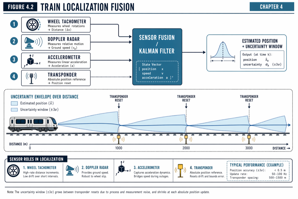
The VOBC runs a fusion algorithm that combines the three sensor inputs into a single best-estimate position with an associated uncertainty. The basic logic is: tachometer provides high-resolution incremental distance; Doppler radar provides independent speed verification and slip-and-slide correction; balise reads provide periodic absolute resets that bound accumulated error.
Between balise reads, the position estimate accumulates uncertainty as the train moves. The growth rate depends on the quality of the tachometer-Doppler agreement: when they agree closely, uncertainty grows slowly (perhaps 0.1 percent of distance traveled); when they disagree, the VOBC takes the more conservative (further-back) estimate and reports growing uncertainty to the wayside Zone Controller. The Zone Controller incorporates this uncertainty into the safe-following distance calculation, effectively trading capacity for confidence.
When the train passes a balise, the absolute position is reset and the uncertainty collapses to a small fixed value (typically 0.5 meter, set by the balise’s surveyed installation tolerance). The system then begins accumulating uncertainty again until the next balise read. This is the core of why balise spacing matters: closer spacing means tighter uncertainty bounds, which means less conservative Movement Authorities, which means tighter achievable headways.
In normal operation on a well-instrumented metro line, the system reports localization accuracy of one to two meters, with sub-second update cadence to the wayside. (For how the wayside uses this position to compute authority, see The Movement Authority Concept: How a CBTC Train Decides How Far to Go.)
Failure modes and how the architecture handles them
Each sensor can fail; the architecture is designed to degrade rather than break.
If a single tachometer fails (most modern installations carry two or four, one per bogie), the VOBC detects the discrepancy through cross-comparison with the others and the Doppler radar. The faulty sensor is excluded; localization continues with marginally larger uncertainty. The driver is notified through the DMI; maintenance is scheduled at the next available service window.
If the Doppler radar fails, the system loses its primary slip-and-slide check. Localization continues on tachometer-plus-balise, but in adverse weather conditions the VOBC may report increased uncertainty, and the Zone Controller may extend safe-following margins accordingly. Capacity drops modestly; safety is preserved.
If the train misses a balise read — perhaps because debris on the antenna or in the trackbed — the VOBC continues dead-reckoning until the next balise. Uncertainty grows, but the next balise (a few hundred meters later) restores the absolute fix. A single missed balise rarely causes operational impact; missed reads at multiple consecutive balises trigger a defined fallback that may include service braking and operator intervention.
If the entire localization stack on a single train fails — for example, a software fault disabling sensor fusion — the VOBC enters a safe state, applies the brake, and reports the failure to the wayside. The line continues for every other train; the failed train is moved manually under direct dispatcher supervision. This is the worst case for that train but a routine event for the line.
Why some systems still keep track circuits
A surprising fact about US CBTC deployments is that most retrofit projects retain track circuits in some form, even though the moving-block architecture does not need them for normal operation. Three reasons.
First, broken-rail detection. Track circuits inherently detect broken rail because a break opens the electrical circuit. CBTC localization does not detect broken rail; the architecture relies on independent broken-rail detectors or retained track circuits to do so.
Second, unequipped vehicle detection. Engineering work trains, hi-rail vehicles, and any rolling stock not yet retrofitted with a VOBC do not appear in the CBTC position model. Track circuits detect them and prevent CBTC trains from being granted Movement Authorities into occupied territory.
Third, fallback during cutover. During the multi-year period of mixed-fleet overlay operation, track circuits provide the legacy occupancy model that CBTC and non-CBTC trains can both rely on. (For the strategic implications of mixed-fleet operation, see CBTC vs Traditional Signaling: 8 Concrete Differences.)
Practical takeaways
- CBTC localization fuses tachometer, Doppler radar, and balise data; no one sensor is sufficient alone.
- GPS is not used as the primary positioning source on any urban CBTC line because tunnels, urban canyons, and integrity certification all rule it out.
- Balise spacing is a tunable design parameter that trades wayside infrastructure cost against achievable headway. Closer spacing equals tighter uncertainty equals better capacity.
- Localization uncertainty grows between balise reads and resets at each one. The Zone Controller incorporates this uncertainty into Movement Authority generation; sloppy localization equals conservative authority equals lost capacity.
- Most US retrofits retain track circuits for broken-rail detection, unequipped-vehicle detection, and overlay-period fallback. Specify this explicitly in the RFP.
Where to go next
This post is a 10-minute summary. The full treatment lives in [Chapter 4 — Onboard Equipment] of Communications-Based Train Control (Volume 1 on Amazon). Download Chapter 4 slides (free PDF →)
Sources
- Wang, C. (2026). Communications-Based Train Control, Volume 1: Foundations & Technical Architecture. Independent. ISBN 979-8-258-54295-3. — Chapter 4, “Onboard Equipment”; Chapter 5, “Wayside Equipment.”
- IEEE Standards Association. IEEE Std 1474.3: Standard for Communications-Based Train Control (CBTC) System Design and Functional Allocations.
- International Electrotechnical Commission. IEC 62290-2: Railway applications — Urban guided transport management and command/control systems — Part 2: Functional requirements specification.
- Federal Railroad Administration. Positive Train Control Implementation Reports. railroads.dot.gov/program-areas/safety/ptc (background context only)
- MTA New York City Transit. L Line CBTC Project Documentation. new.mta.info
- HART (Honolulu Authority for Rapid Transportation). Skyline System Description. honolulutransit.org
Read the full treatment in the book
Chapter 4 of Communications-Based Train Control, Volume 1, covers this in depth.