definitional · Article
Moving Block Explained: Why It Replaced Fixed Block
When the RATP commissioned Paris Métro Line 14 in October 1998, it became the first revenue metro in the world to operate entirely on a moving-block control system. The line was greenfield, the rolling stock was uniform, and the platforms had screen doors from day one. None of that was an accident. RATP designed the line specifically to demonstrate that the moving-block paradigm — a concept that had circulated in academic and vendor literature for two decades — could be made to work at full revenue scale. Nearly 30 years later, every CBTC system worldwide is built on the same idea. This post explains what moving block actually is, where the headway gain comes from mathematically, and what trades the architecture imposes that vendor brochures rarely advertise.
Why this matters
For a transit agency program manager, “moving block” is often the magic phrase that justifies a multi-hundred-million-dollar capital request. That makes it worth understanding precisely. Moving block is not a marketing term; it is a specific algorithm for computing safe train separation. It replaced fixed block because it lifts the capacity ceiling on dense urban metros without buying additional right-of-way or rolling stock. But it imposes its own constraints: high-precision localization, reliable bidirectional communication, and a vendor-managed real-time control loop that runs at sub-second cadence. This post is for the engineer or planner who needs to follow a vendor’s capacity claim through the math, the standards, and the deployed evidence.
Fixed block, briefly
A fixed-block system divides the track into discrete sections, typically 100 to 500 meters long. A track circuit detects whether each block is occupied. The signaling rule is simple and unambiguous: a train cannot enter a block until the preceding train has fully cleared it. The minimum following distance therefore equals one block length, plus the train’s braking distance from current speed, plus the operator’s reaction time, plus margins.
The granularity of the fixed-block system is its block length. With 300-meter blocks and a typical urban metro speed of 22 mph, the calculated minimum headway is around 12 seconds — but that is the theoretical floor. Real-world operation, including dwell time variability, infrastructure unreliability, and signaling cycle latency, pushes the achievable peak frequency to roughly 24 to 28 trains per hour per direction on the busiest US metro lines. That is the ceiling that has constrained New York’s Lexington Avenue Line, BART’s transbay tube, and Chicago’s Red Line for decades. (For the side-by-side, see CBTC vs Traditional Signaling: 8 Concrete Differences.)
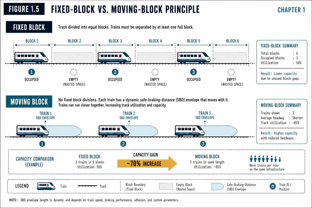 Fixed block reserves a track section in advance of the train; moving block sets a virtual buffer continuously around the train.
What moving block actually computes
A moving-block system abandons fixed sections entirely. Instead, the wayside Zone Controller computes, for each train and updated every cycle, a continuously moving safe-following distance. The computation is approximately:
Safe Following Distance = Braking Distance at Current Speed + Communication and Localization Margin + Lead-Train Position Uncertainty + Engineering Safety Margin.
Each term is concrete. Braking distance comes from the train’s certified service-brake performance and current speed; on a typical metro train at 50 km/h, this is roughly 80 meters. The localization margin captures the worst-case error in the lead train’s reported position, which depends on time since the last balise read; modern systems carry this at one to two meters. The position uncertainty term accounts for radio latency: a position reported a moment ago has effectively moved further by the time the wayside acts on it. The engineering safety margin is fixed by the safety case, often 20 to 30 meters for metro applications.
Every term in this computation either shrinks (because the train is going slowly) or grows (because the train is at higher speed) in real time. The wayside re-issues a fresh Movement Authority every one to three seconds. (For the underlying authority concept, see The Movement Authority Concept: How a CBTC Train Decides How Far to Go.)
Where the headway gain comes from
The capacity gain from moving block is the difference between two formulas. In fixed block, minimum separation is the block length plus braking distance. In moving block, minimum separation is the braking distance plus margins, with no block-length term.
For a metro train at typical operating speed, the braking distance dominates the moving-block sum. The block length, in fixed-block territory, often dominates the fixed-block sum. Removing the block-length term recovers a substantial fraction of the achievable headway. In deployed practice, this translates to a 20 to 40 percent capacity uplift on retrofitted urban metros: the L Line moved from roughly 20 to 29 trains per hour per direction; Paris Métro Line 1 from roughly 20 to 27; Hong Kong’s Tsuen Wan Line from 18 to 24; Singapore’s Circle Line from 15 to 25 in greenfield deployment.
The capacity gain is not free, and it is not unbounded. The minimum theoretical headway in moving block is constrained by station dwell time, not by signaling. Once a line approaches 30-second dwells and 80-second headways, the limiting factor becomes how fast passengers board and alight, not how fast the wayside computes a Movement Authority. Signaling can take an agency from the fixed-block ceiling to the dwell ceiling; it cannot move the dwell ceiling.
The hidden prerequisites
Moving block is conceptually simple but operationally demanding. Three prerequisites have to be in place for the architecture to work, and each one drives capital cost and project complexity.
The first is high-resolution localization. The train must know where it is to within roughly one to two meters at all times. CBTC localization fuses tachometer pulses, Doppler radar ground-speed measurement, and balise reads (passive transponders embedded in the trackbed at known positions). Each technology corrects the others’ weaknesses: tachometers drift on wheel slip and slide; Doppler radar handles speed but not absolute position; balises give absolute position fixes only when the train passes one. (For the full localization picture, see How CBTC Trains Know Where They Are (Without Track Circuits).)
The second is continuous bidirectional communication. The Data Communication System (DCS) carries position reports from train to wayside and Movement Authorities back the other way, dozens of times per minute, with cryptographic authentication and overlapping radio coverage. A moving-block line that loses radio for more than a few seconds applies brakes; the architecture is intolerant of communication gaps in a way that fixed block, with its inherent local fallback to track-circuit detection, is not.
The third is distributed vital processing. Both the onboard Vehicle On-Board Controller (VOBC) and the wayside Zone Controller must be Safety Integrity Level 4 certified under IEC 61508. SIL 4 imposes redundant hardware, diverse software implementations, formal verification, and a development lifecycle that adds substantial nonrecurring engineering cost. (The functional layers running on these processors are detailed in ATP, ATO, ATS: The Three-Layer Triad of Modern Train Control.)
Failure modes worth understanding
Moving block fails differently than fixed block, and the failure modes shape the operational reality.
If a single train loses radio contact, that train’s onboard ATP applies service brakes within a configurable timeout (typically three to five seconds), bringing it to a controlled stop within its last valid Movement Authority. The rest of the line continues at full performance. This is graceful single-train degradation.
If a Zone Controller fails, its hot-standby takes over within roughly 500 milliseconds. Trains do not see the takeover; the heartbeat between primary and standby controllers ensures continuous coverage of the zone. This is graceful infrastructure degradation.
If wider radio coverage fails — a 2.4 GHz interference event, a fiber backhaul cut, a software fault propagating across zones — the system falls back to a defined restricted-manual mode. Operators take direct control under ATP supervision; capacity drops 15 to 25 percent rather than the 50 to 60 percent collapse typical of fixed-block manual block working.
There is one failure mode worth special attention: the phantom train. A CBTC system can only protect against trains it knows about. An engineering work train that was towed onto the line without registering with the wayside, or a CBTC train whose VOBC has failed silently, becomes invisible. The system response is to keep secondary track-circuit fallback active in CBTC territory specifically to detect “unauthorized” occupancy. This is one of the reasons most US deployments retain track circuits in some form rather than ripping them out entirely.
Practical takeaways
- Moving block computes a virtual buffer continuously, not a fixed reservation. The headway gain is the difference between “block length plus braking distance” and “braking distance plus margins.”
- The capacity uplift on retrofitted urban metros is typically 20 to 40 percent. The L Line and Paris Line 1 are the public reference points.
- Three prerequisites — localization, communication, and SIL 4 distributed processing — drive most of the project’s cost and complexity. Underspecify any one and the architecture does not work.
- Degraded modes are graduated, not blunt. Single-train, zone-controller, and wider failures each have defined responses; capacity does not collapse all at once.
- Track-circuit fallback is not vestigial. It detects unauthorized occupancy and broken rail, and most US deployments specify it explicitly in retrofit RFPs.
Where to go next
This post is a 10-minute summary. The full treatment lives in [Chapter 1 — The Evolution of Train Control] and [Chapter 5 — Wayside Equipment] of Communications-Based Train Control (Volume 1 on Amazon). Download Chapter 1 slides (free PDF →)
Sources
- Wang, C. (2026). Communications-Based Train Control, Volume 1: Foundations & Technical Architecture. Independent. ISBN 979-8-258-54295-3. — Chapter 1, “The Evolution of Train Control”; Chapter 5, “Wayside Equipment.”
- IEEE Standards Association. IEEE Std 1474.1: Standard for Communications-Based Train Control (CBTC) Performance and Functional Requirements.
- International Electrotechnical Commission. IEC 62290-1: Railway applications — Urban guided transport management and command/control systems — Part 1: System principles and fundamental concepts.
- RATP. Paris Métro Line 14 Project Overview. ratp.fr
- MTR Corporation. Tsuen Wan Line Resignaling. mtr.com.hk
- MTA New York City Transit. L Line CBTC Performance Reports. new.mta.info
- Land Transport Authority of Singapore. Circle Line Project Overview. lta.gov.sg
Read the full treatment in the book
Chapter 1 of Communications-Based Train Control, Volume 1, covers this in depth.